Split flange V-groove and anti-rotation mating system

a technology of v-groove and flange, which is applied in the direction of machines/engines, stators, liquid fuel engines, etc., can solve the problems of high cost of assembling and disassembling parts, and high cost of manufacturing parts

Active Publication Date: 2007-07-12
RTX CORP
View PDF2 Cites 23 Cited by
  • Summary
  • Abstract
  • Description
  • Claims
  • Application Information

AI Technical Summary

Benefits of technology

[0008] In accordance with the present invention, there is provided a turbine engine component broadly comprising an annular flange, at least one element to be mated to the flange, and mating means for joining the at least one element to the flange. The mating means includes a first annular groove in the flange, which groove has two opposed planar wall portions for preventing axial movement of the at least one element relative to the flange. In a preferred embodiment, the mating means also includes a second annular groove in the flange. A sealing element is positioned within the second annular groove.

Problems solved by technology

Due to the complexity of the parts and the little room for mechanics to assemble them, the cost of assembling and disassembling the parts can be great.
Additionally, the cost of manufacturing the parts can be significant.

Method used


Image

  • Split flange V-groove and anti-rotation mating system
  • Split flange V-groove and anti-rotation mating system
  • Split flange V-groove and anti-rotation mating system

Examples


Embodiment Construction

)

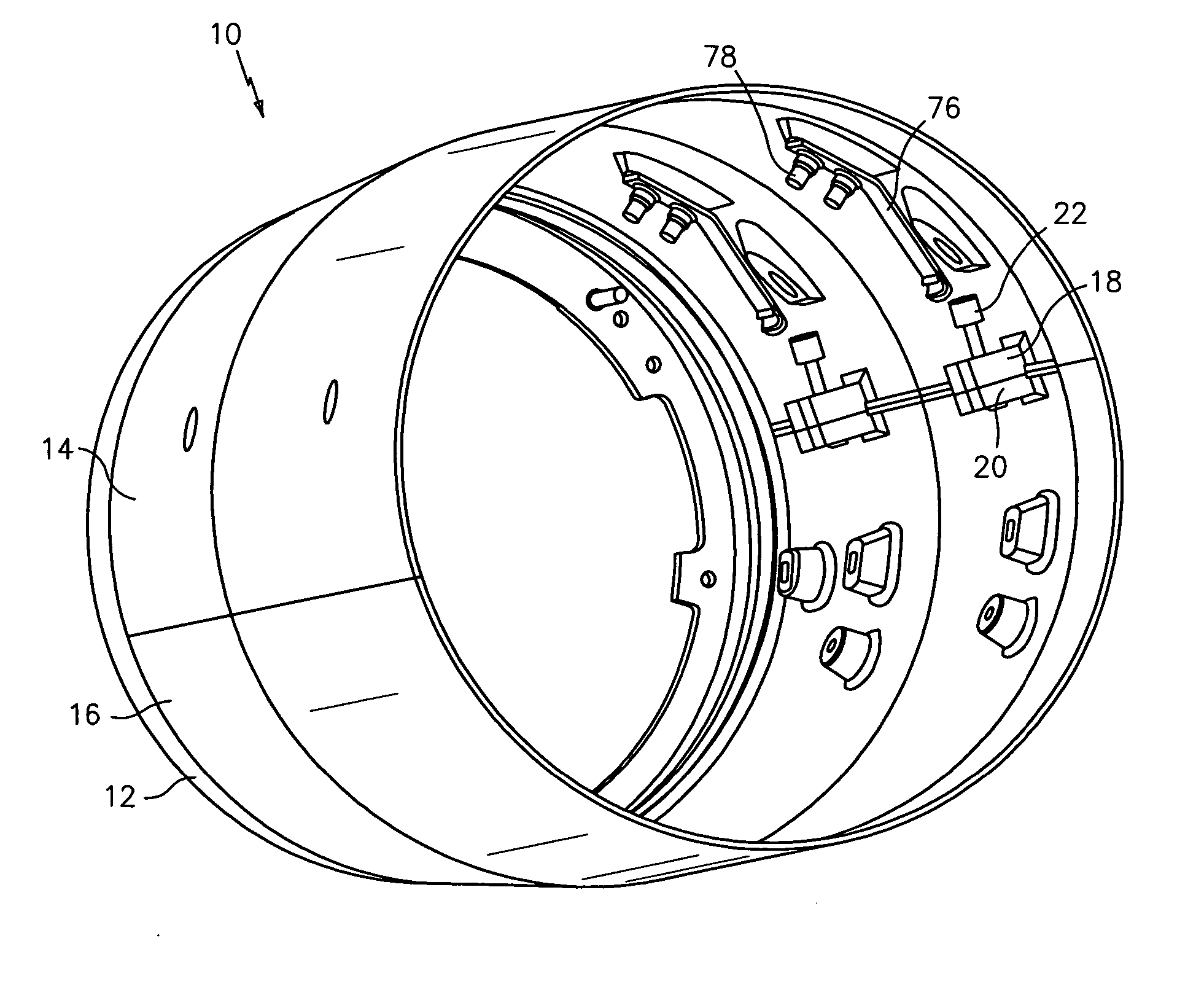
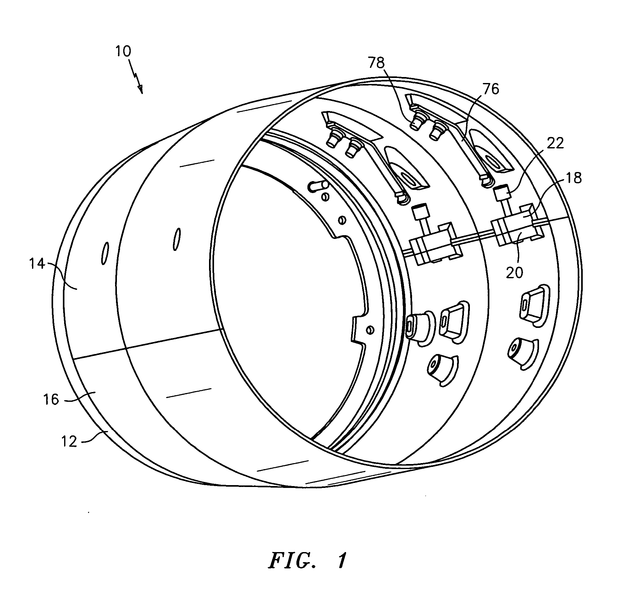
[0022] Referring now to the drawings, FIG. 1 illustrates a turbine engine component 10, such as a duct pipe in which a drive assembly (not shown) may be positioned. The turbine engine component 10 includes a full hoop or annular flange 12 to which duct pipe halfs 14 and 16 are attached. Each duct pipe half 14 and 16 has a half hoop or semi-annular configuration. The duct pipe half 14 has a plurality of spaced apart split flanges 18. The duct pipe half 16 has a plurality of mating spaced apart split flanges 20 which abut the flanges 18 when the duct pipe halfs 14 and 16 are assembled and abut each other. As will be discussed later, a fastener 22, such as a bolt or screw, may be used to join each pair of split flanges 18 and 20, and thus the duct pipe halfs 14 and 16, together.

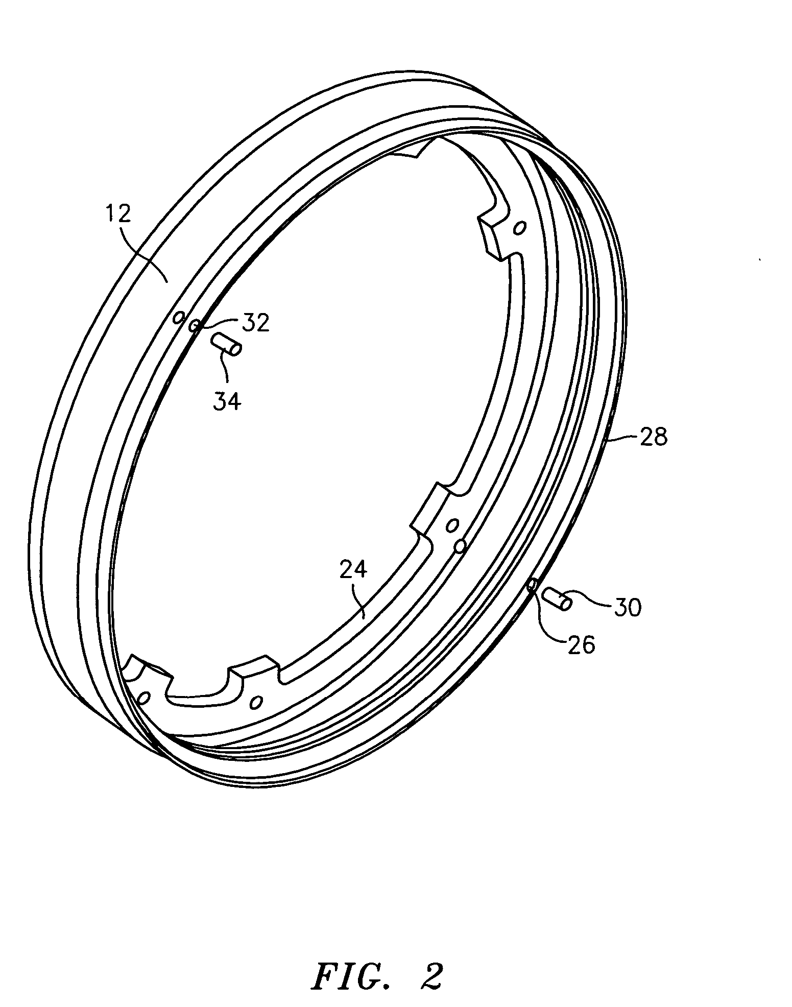
[0023] The full hoop or annular flange 12 used in the component 10 is illustrated in FIG. 2. The flange 12 includes an annular internal wall structure 24. The flange 12 also has a first slot 26 machined in a l...


PUM


Abstract

There is provided a turbine engine component, such as a duct pipe, comprising an annular flange, at least one element, such as two duct pipe halfs, to be mated to the flange, and mating system for joining the at least one element to the flange. The mating system includes a first annular groove in the flange, which groove has two opposed planar wall portions for preventing axial movement of the at least one element relative to the flange. In a preferred embodiment, the mating system also includes a second annular groove in the flange. A sealing element is positioned within the second annular groove.

Description

STATEMENT OF GOVERNMENT INTEREST [0001] The Government of the United States of America may have rights in the present invention as a result of Contract No. N00019 02 C 3003 awarded by the Department of the Navy.BACKGROUND OF THE INVENTION [0002] (1) Field of the Invention [0003] The present invention relates to a mating system for joining together various parts of a turbine engine component. [0004] (2) Prior Art [0005] Turbine engine components are often formed by multiple parts which have to be joined together. Most frequently, the parts are joined together by a plurality of fasteners. Due to the complexity of the parts and the little room for mechanics to assemble them, the cost of assembling and disassembling the parts can be great. Additionally, the cost of manufacturing the parts can be significant. [0006] There is needed a mating system for joining various parts of a turbine engine component which uses no fasteners in the mating interface and which facilitates removal and asse...

Claims


Application Information

Patent Timeline
Patent Type & Authority Applications(United States)
IPC IPC(8): F04D29/40
CPCF05D2260/33F01D25/243
Inventor WELCH, DAVID A.
Owner RTX CORP
Why Eureka
Try Eureka