Artificial joints using agonist-antagonist actuators

Inactive Publication Date: 2007-07-12
MASSACHUSETTS INST OF TECH
View PDF6 Cites 233 Cited by
  • Summary
  • Abstract
  • Description
  • Claims
  • Application Information

AI Technical Summary

Benefits of technology

[0030] The following summary provides a simplified introduction to some aspects of the invention as a prelude to the mo

Problems solved by technology

None of these systems are able to add energy during the stride to help keep the body moving forward or to reduce impact losses at heel strike.
However, for most applications, the SEA requires a tremendous amount of electric power for its operation

Method used


Image

  • Artificial joints using agonist-antagonist actuators
  • Artificial joints using agonist-antagonist actuators
  • Artificial joints using agonist-antagonist actuators

Examples


Embodiment Construction

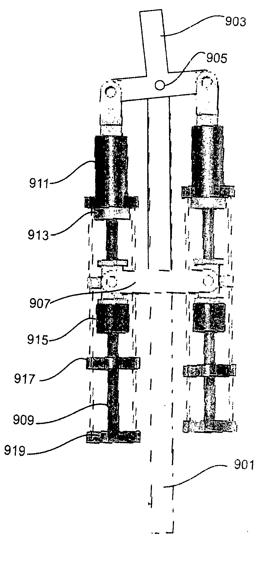
[0070] In the construction of a biologically realistic limb system that is high performance, light weight, quiet and power efficient, a agonist-antagonist actuator design is proposed herein comprising a plurality of actuators and series elastic structures. Since it is desirable to minimize the overall weight of the limb design, the efficiency of the agonist-antagonist actuator design is critical, especially given the poor energy density of current power supplies, e.g. lithium-ion battery technology. By understanding human biomechanics, the lightest, most energy efficient agonist- antagonist actuator design can be achieved.

[0071] In the next section, the key features of biomechanical systems are highlighted. A more complete description of biomechanical systems is found in the patent applications cited in the foregoing “Cross Reference to Related Applications” whose disclosures are incorporated herein by reference.

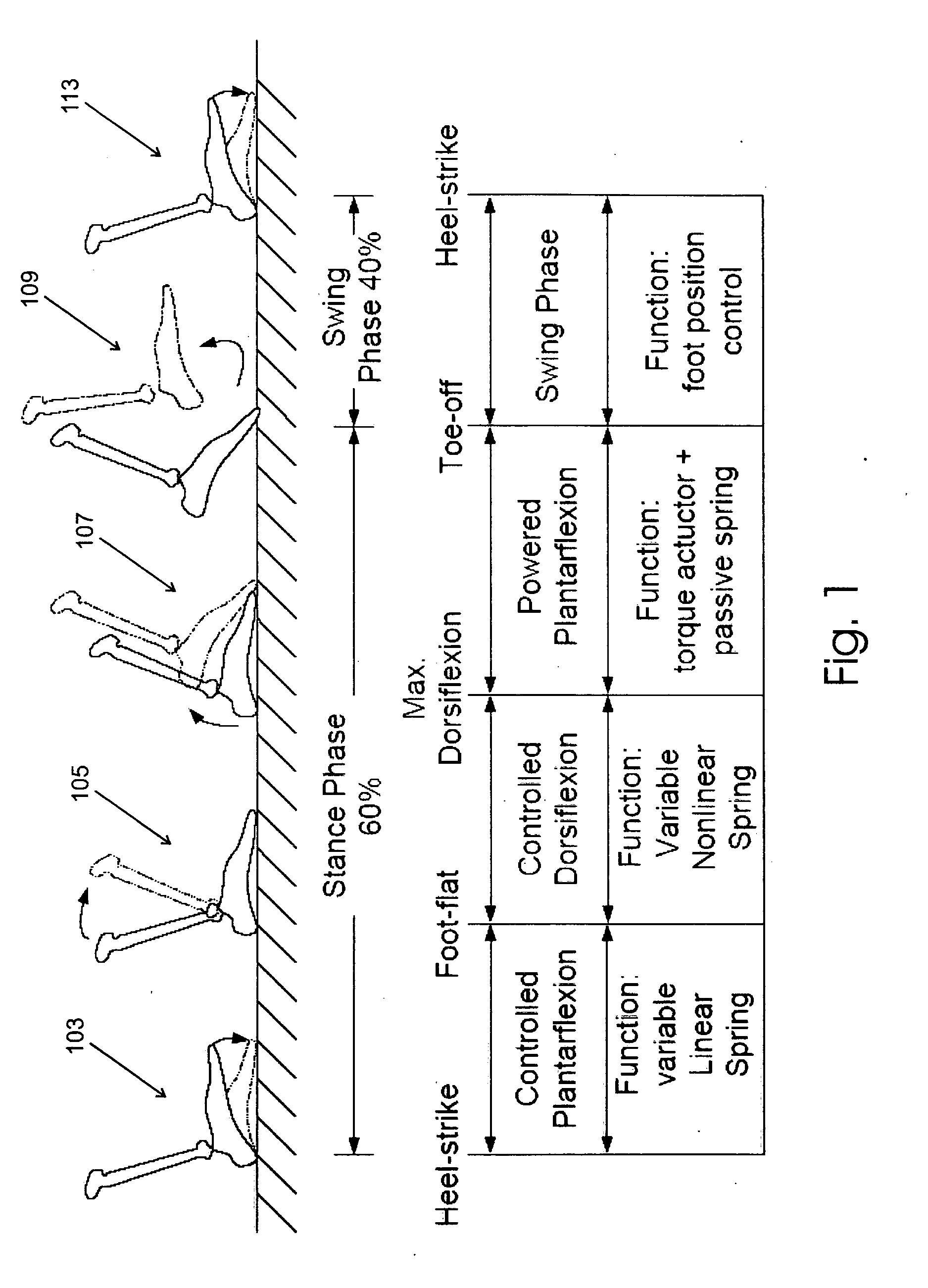
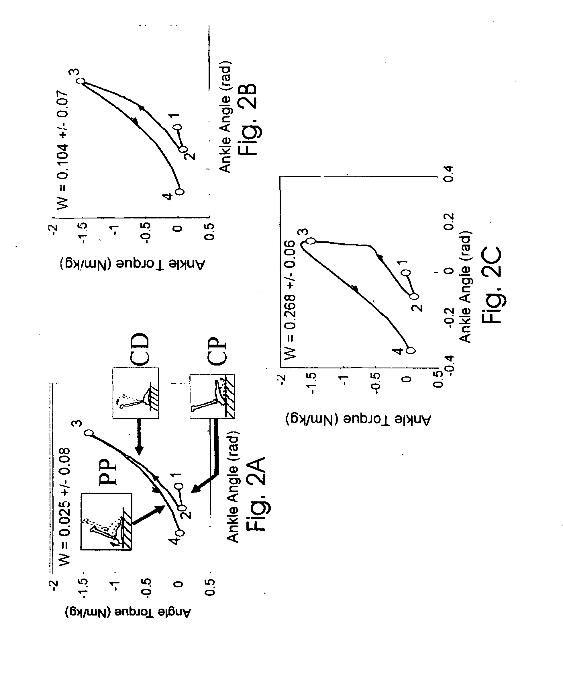
[0072] Joint Biomechanics: The Human Ankle

[0073] Understanding norma...


PUM


Abstract

Artificial limbs and joints which behave like a biological limbs and joints employ a synthetic actuator which consume negligible power when exerting zero force, consume negligible power when outputting force at constant length (isometric) and while performing dissipative, nonconservative work, are capable of independently engaging flexion and extension tendon-like, series springs, are capable of independently varying joint position and stiffness, and exploit series elasticity for mechanical power amplification.

Description

CROSS REFERENCE TO RELATED APPLICATIONS [0001] This application is a non-provisional of U.S. patent application Ser. No. 60 / 751,680 filed on Dec. 19, 2005. [0002] This application is a continuation in part of U.S. patent application Ser. No. 11 / 395,448 entitled “Artificial human limbs and joints employing actuators, springs, and Variable-Damper Elements” filed on Mar. 31, 2006 by Hugh M. Herr, Daniel Joseph Paluska, and Peter Dilworth. application Ser. No. 11 / 395,448 claims the benefit of the filing date of U.S. Provisional patent application Ser. No. 60 / 666,876 filed on Mar. 31, 2005 and the benefit of the filing date of U.S. Provisional patent application Ser. No. 60 / 704,517 filed on Aug. 1, 2005. [0003] This application is also a continuation in part of U.S. patent application Ser. No. 11 / 499,853 entitled “Biomimetic motion and balance controllers for use in prosthetics, orthotics and robotics” filed on Aug. 4, 2006 by Hugh M. Herr, Andreas G. Hofmann, and Marko B. Popovic. appli...

Claims


Application Information

Patent Timeline
IPC IPC(8): A61F2/48A61F2/74
CPCA61F2/60B62D57/032A61F2/64A61F2/6607A61F2/68A61F2/72A61F2002/5003A61F2002/5004A61F2002/503A61F2002/5033A61F2002/5075A61F2002/6657A61F2002/6818A61F2002/701A61F2002/704A61F2002/741A61F2002/7625A61F2002/763A61F2002/7635A61F2002/764A61F2002/7645B25J19/0008A61F2/605A61F2/70A61F2/741
Inventor HERR, HUGH M.MAGNUSSON, LEE HARRISENDO, KEN
Owner MASSACHUSETTS INST OF TECH
Why Eureka
Try Eureka