Jitter measurements for repetitive clock signals

a clock signal and jitter measurement technology, applied in the direction of noise figure or signal-to-noise ratio measurement, instruments, testing circuits, etc., can solve the problems of critical timing of events, circuits that are time dependent, especially susceptible to jitter problems,

Active Publication Date: 2007-07-12
GOOGLE LLC
View PDF5 Cites 9 Cited by
  • Summary
  • Abstract
  • Description
  • Claims
  • Application Information

AI Technical Summary

Benefits of technology

[0010] Therefore, it is an object of the invention to provide a method for measuring jitter in repetitive si

Problems solved by technology

Circuits that are time dependent, particularly when they operate at high frequencies, are especially susceptible to problems of jitter.
Because multiprocessor systems are commonly used, the timing of events is critical.
Any problem with the data bus results in incorrect data at the other end.
As mentioned previously, PLLs are particularly susceptible to jitter.
Small amounts of jitter may go unnoticed, but at high speed, jitter on the PLL causes data transfer errors.
Redesigning the PLL or the system may normally be a

Method used


Image

  • Jitter measurements for repetitive clock signals
  • Jitter measurements for repetitive clock signals
  • Jitter measurements for repetitive clock signals

Examples


Embodiment Construction

[0025] The invention provides a solution to the above problems by way of a novel method for measuring the jitter and assessing its effect. The ensuing analysis and evaluation will be described using for illustrative purposes only, a Teradyne tester J973. The concept applies to other test platforms besides the Teradyne tester and other waveforms besides PLL clock signals.

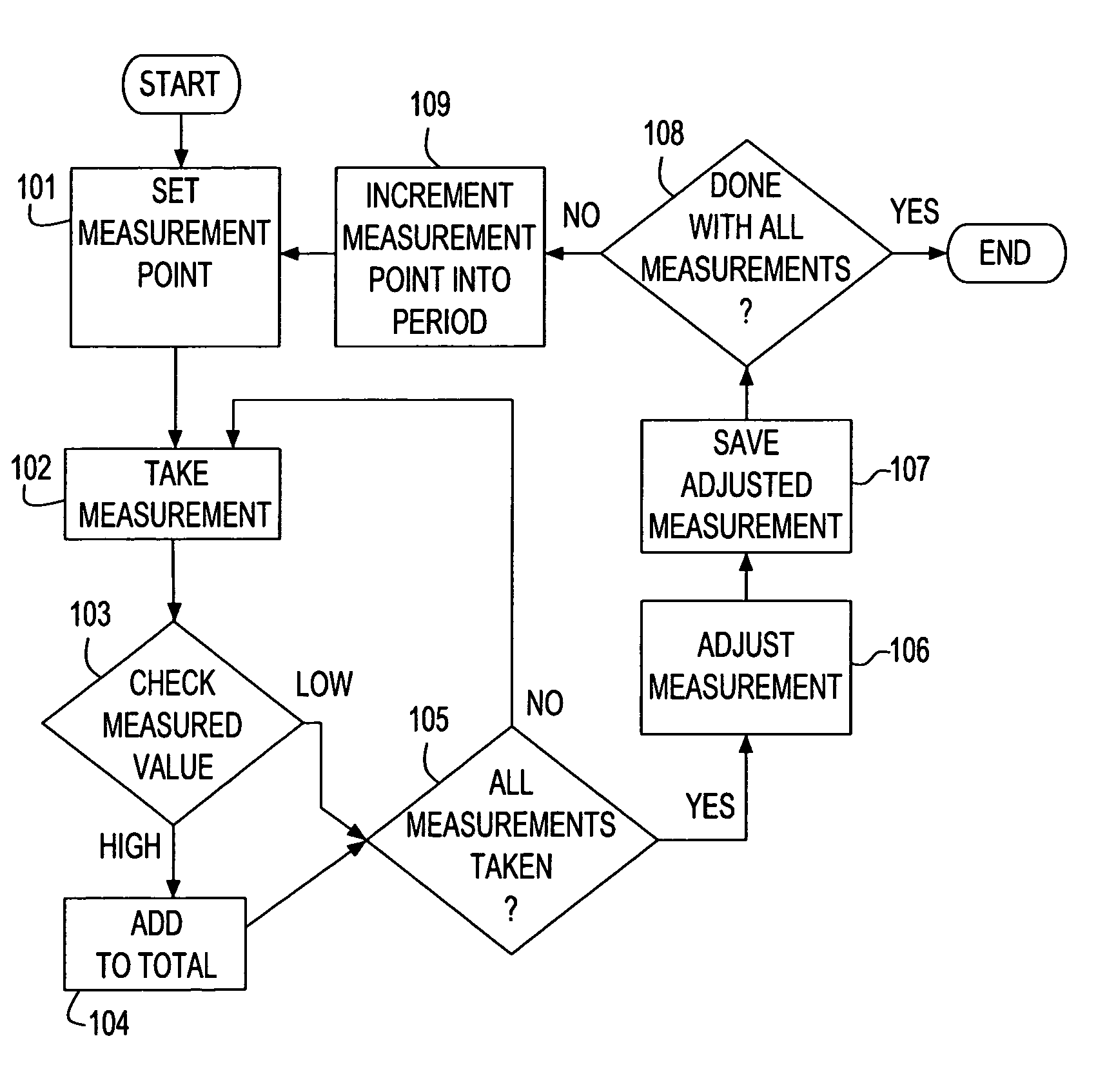
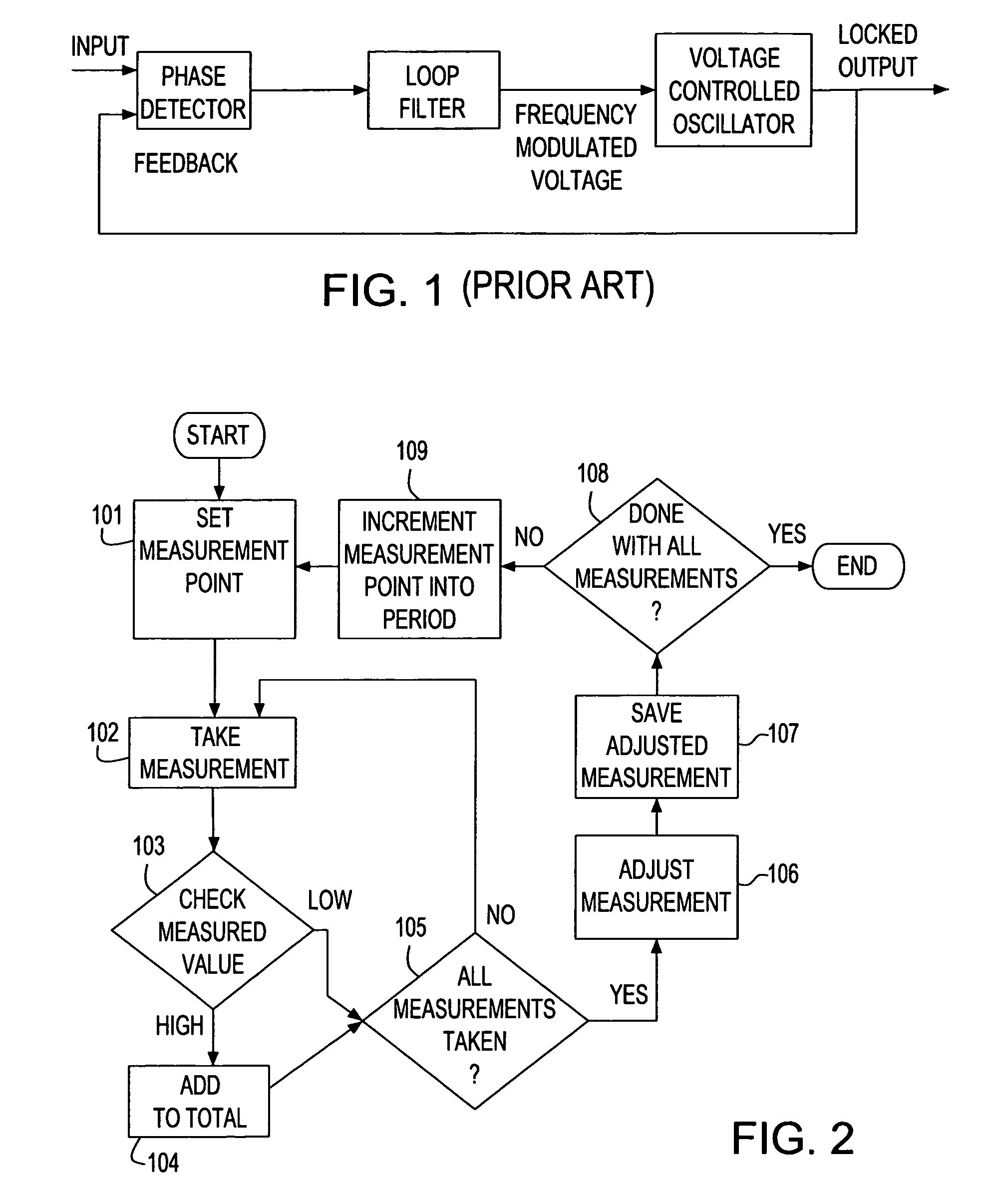
[0026] The basic flow chart representing the preferred embodiment of the present invention is illustrated in FIG. 2. Shown are the actual steps to perform the necessary measurements. Alongside with the step embodying the present invention will also be shown accompanying examples to provide a proper understanding of what happens at the various steps.

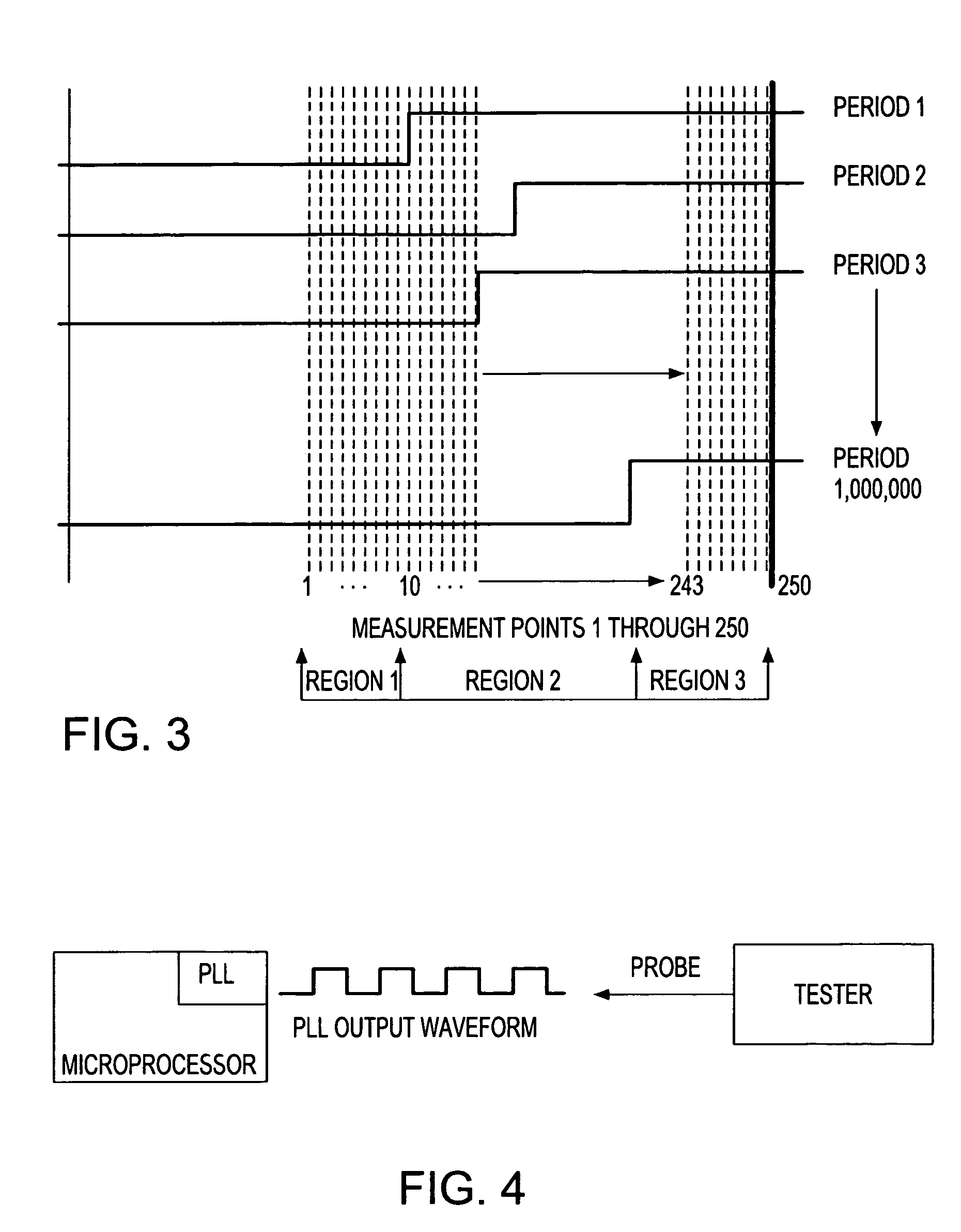
[0027] While the invention is preferably used to measure the jitter on any repetitive pulse string, for illustrative purposes, a phase locked loop (PLL) circuit will be used. The measurement of jitter will be performed on the tester, as previously stated.

[0028] The test...


PUM


Abstract

A system and a method for measuring and quantitatively analyzing the jitter in repetitive electrical signals in a chip using a tester are described. The tester sorts chips based on the jitter measurements, thereby eliminating the need for external instrumentation. The waveform is sampled by the tester at various points of a period over a large number of periods and results are collected. The data is analyzed to determine the total range where the waveform is found to undergo a transition. The transition area is further analyzed to pinpoint the precise location of the transition for each period of the repetitive waveform. The data is used to quantify the jitter by means of statistical analyses, the results of which are used by the tester to sort the chips by comparing the calculated jitter characteristics to predetermined criteria.

Description

BACKGROUND OF THE INVENTION [0001] The invention relates to a system and method for measuring jitter in repetitive electrical signals, and more particularly, to measuring and quantitatively analyzing the jitter in clock signals using a tester to easily sort chips based on the jitter measurements, thereby eliminating the need for external instrumentation. [0002] A phase-locked loop (PLL) is a component that is commonly used in many circuit designs. A circuit of this kind typically synchronizes an input signal to an output signal. It operates such that the output signal tracks the input signal in phase or relative position of the waveform. The frequency can be the same, or by means of a divider or multiplier circuit, the input and output frequency may differ while still being synchronized in-phase. Jitter of the output of the clock signal in a PLL determines the quality and even the performance of the output signal and of any circuit depending thereof. Therefore, jitter measurements i...

Claims


Application Information

Patent Timeline
IPC IPC(8): G01R29/26
CPCG01R31/31709
Inventor FOSTER, SAMUEL A.MOTIKA, FRANCO
Owner GOOGLE LLC
Why Eureka
Try Eureka