Supercooling apparatus, refrigerator, and control method thereof

Inactive Publication Date: 2007-07-19
SAMSUNG ELECTRONICS CO LTD
View PDF12 Cites 44 Cited by
  • Summary
  • Abstract
  • Description
  • Claims
  • Application Information

AI Technical Summary

Benefits of technology

[0015] Accordingly, it is an aspect of the present invention to provide a refrigerator, which can maintain a storage for a beverage at an optimal temperature to stably supercool the beverage and then maintain

Problems solved by technology

However, such a slush beverage is insufficient to satisfy demands of a user due to a problem in that such a slush beverage is inconvenient to have due to a large size of ice particles, and tends to change in its flavor due to dilution of the beverage as time passes.
When the water is in the supercooled state, it is relatively unstable since the water has a higher free energy than water in the solid state.
As a result, it is very difficult to maintain the beverage in the supercooled state.
In the point of view as described above, it is very difficult for the conventional refrigerator to produce a slush beverage by supercooling the beverage.
Specifically, every beverage has its own supercooling degre

Method used


Image

  • Supercooling apparatus, refrigerator, and control method thereof
  • Supercooling apparatus, refrigerator, and control method thereof
  • Supercooling apparatus, refrigerator, and control method thereof

Examples


first embodiment

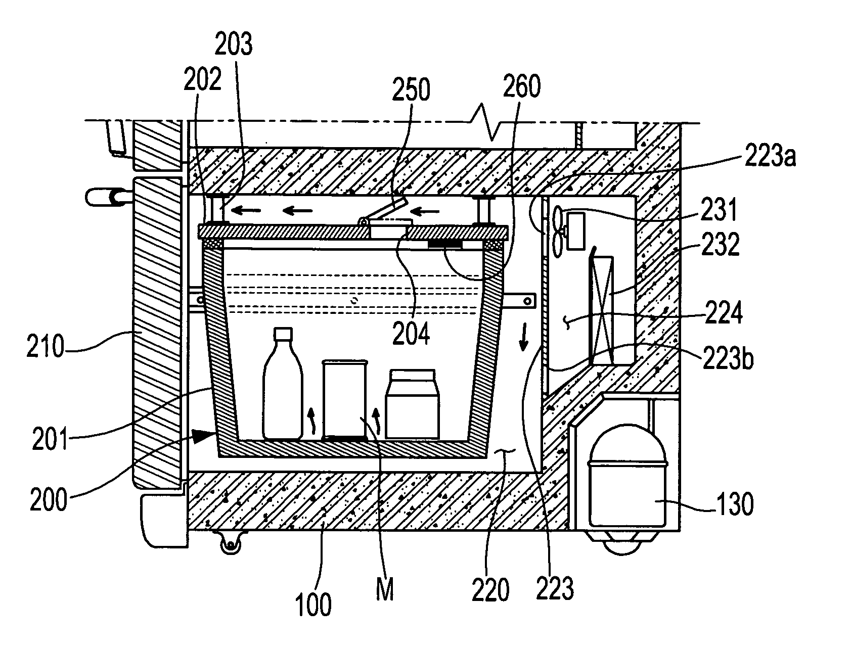
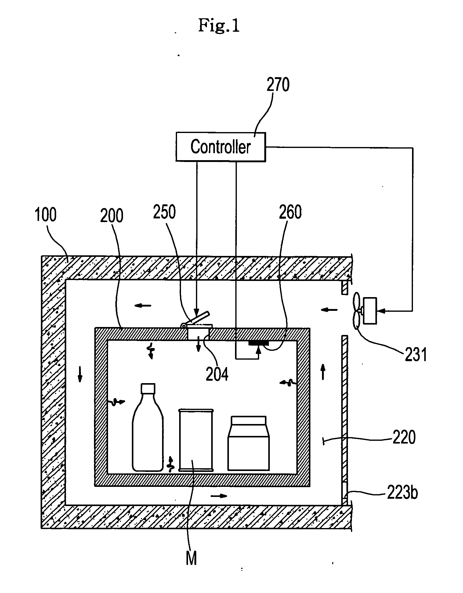
[0074]FIG. 3 shows a refrigerator which includes a separate evaporator 232, and a separate fan 231 in order to control the supercooling apparatus independently of a freezing compartment or a refrigerating compartment. FIGS. 3 and 4 show the structure wherein the chilled air is supplied from a freezing compartment 120 to the storage 220 via a duct 233 and the fan 231. Here, the freezing compartment 120 is provided with a freezing air supply unit 121 which includes an evaporator 122 for the freezing compartment. Specifically, FIG. 3 shows the structure wherein the duct 233 serving to guide the chilled air to the storage 220 is communicated with the freezing compartment 120 such that the chilled air is supplied from the freezing compartment 120 to the storage 220 via the duct 233. FIG. 4 shows the structure wherein the storage 220 is in direct communication with the freezing air supply unit 121 such that a portion of chilled air generated by the evaporator 122 for the freezing compart...

third embodiment

[0089] Meanwhile, in the third embodiment shown in FIG. 5, a duct 233 is provided to communicate the freezing compartment 120 with the chilled air supply part 224. Thus, instead of inducing the chilled air from the freezing chilled air supply part 121, this embodiment induces the chilled air from the freezing compartment 120 into the storage 220.

[0090] In the embodiments shown in FIGS. 4 and 5, stopping the supply of the chilled air into the storage 220 is achieved by stopping operation of the fan 231. The duct 233 may be provided with an opening and closing member 234 to open or close an inlet or an outlet of the duct 233 such that the opening and closing member closes the duct 233 at the same time when the fan 231 is stopped. Alternatively, the opening and closing member 234 may be provided to open or close the communication hole 223a for the same function instead of opening or closing the duct 233.

[0091] Meanwhile, the partition plate 223 is further formed with an air flow hole ...

fourth embodiment

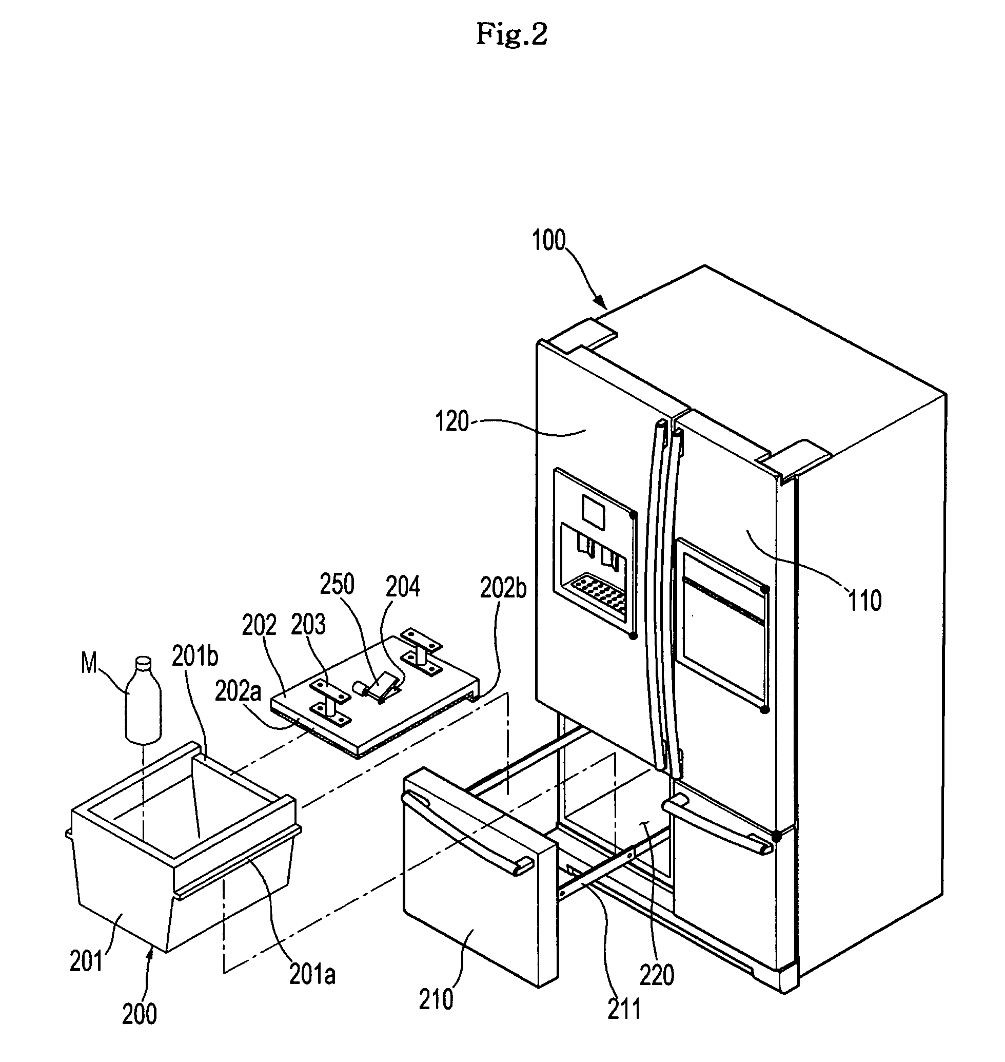
[0094] Referring to FIG. 8, a refrigeration according to the invention includes a body 100 defining an overall appearance of the refrigerator, a refrigerating compartment 110 and a freezing compartment 120 defined in the body 100, and a storage 220 independent of the refrigerating compartment 110 and the freezing compartment 120. The storage 220 has a supercooling compartment 200 defined therein and formed of a material having a large heat capacity.

[0095] Although the refrigerator is illustrated in FIG. 8 as having a drawer type door 210 to open or close the storage 220, the present invention is not limited to this structure. Alternatively, the storage 220 may be provided with a hinge type door hingably attached to one side, an upper or lower side of an opening of the storage 220. In the structure wherein the drawer type door 210 is provided to the storage 220 such that the supercooling compartment 200 is received in the storage 220 as shown in FIG. 8, the door 210 is provided with ...


PUM


Abstract

A refrigerator for storing a beverage at an optimal temperature to stably supercool the beverage and maintain the beverage in a supercooled state, and that can rapidly produce a supercooled beverage while maintaining the supercooled state of the beverage. A supercooling apparatus of the refrigerator includes a storage to which chilled air is supplied from a chilled air supply unit, a supercooling compartment positioned in the storage and refrigerated by the chilled air to indirectly refrigerate an object therein, a hole formed at one side of the supercooling compartment to allow flow of the chilled air into and from the supercooling compartment, and a damper to open or close the hole. The object is directly or indirectly refrigerated in the supercooling compartment according to user's selection by opening or closing the damper.

Description

CROSS-REFERENCE TO RELATED APPLICATIONS [0001] This application claims the benefit of Korean Patent Application No. 2006-0004205, filed on Jan. 14, 2006 in the Korean Intellectual Property Office, the disclosure of which is incorporated herein by reference. BACKGROUND OF THE INVENTION [0002] 1. Field of the Invention [0003] The present invention relates to a refrigeration compartment, a refrigerator including the same, and a control method thereof. More particularly, the present invention relates to a refrigerator including an independent refrigeration compartment which can supercool a beverage and maintain a supercooled state of the beverage, and a method for controlling the refrigerator such that a variation in temperature of the refrigeration compartment is minimized to maintain the supercooled state of the beverage. [0004] 2. Description of the Related Art [0005] With advances in refrigerator technology, requests for cool and tasty beverages has been initially satisfied by ice c...

Claims


Application Information

Patent Timeline
IPC IPC(8): F25D17/04F25D11/02
CPCF25D17/045F25D17/065F25D31/007F25D2700/121F25D2317/0665F25D2400/28F25D2317/061F25D25/025F25D17/08B60J3/002B60J3/0213B60J1/02B60J1/20
Inventor SHIN, YOUNG SHIKLEE, JAE SEUNGHAHM, KYUNG HEELEE, HYE RANLIM, CHANG HAKLIM, JUNG SOOHA, JOO YOUNGKIM, YONG HANYOON, WON JAEKIM, JEONG HAN
Owner SAMSUNG ELECTRONICS CO LTD
Why Eureka
Try Eureka