Terminal apparatus, method and computer readable recording medium

a technology of terminal equipment and recording medium, which is applied in the direction of two-way working systems, instruments, television systems, etc., can solve the problems of increasing the load of communication traffic, deteriorating image quality of moving pictures, and long time required for transferring data on networks, so as to achieve the effect of not deteriorating image quality of network cameras

Active Publication Date: 2007-07-19
PANASONIC I PRO SENSING SOLUTIONS CO LTD
View PDF5 Cites 65 Cited by
  • Summary
  • Abstract
  • Description
  • Claims
  • Application Information

AI Technical Summary

Benefits of technology

[0013]As a consequence, the present invention has an object to provide a terminal apparatus capable

Problems solved by technology

On the other hand, in such network camera systems, in order that images having high resolution of Motion JPEG and JPEG formats are acquired to be displayed on image viewers, lengthy time is required for transferring data on networks.
In particular, in the case of a moving picture of the Motion JPEG format, the moving picture is adversely influenced by traffic of the network, and thus, an image quality as the moving picture is also deteriorated.
Also, even when a user can obtain an image having high resolution, the user may eventually receive useless data, and also, such data, only the partial data of which is required and the remaining data of which is not required, may increase loads of communication traffi

Method used


Image

  • Terminal apparatus, method and computer readable recording medium
  • Terminal apparatus, method and computer readable recording medium
  • Terminal apparatus, method and computer readable recording medium

Examples


embodiment 1

[0026]A description is made of a terminal apparatus according to an embodiment 1 of the present invention, and furthermore, a program used for this communication terminal apparatus. Then, a network camera of the embodiment 1 includes a remote controlled camera such as a monitoring camera.

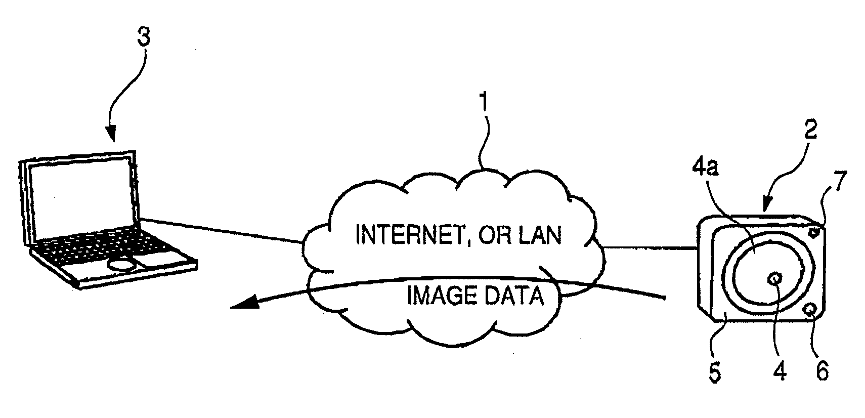
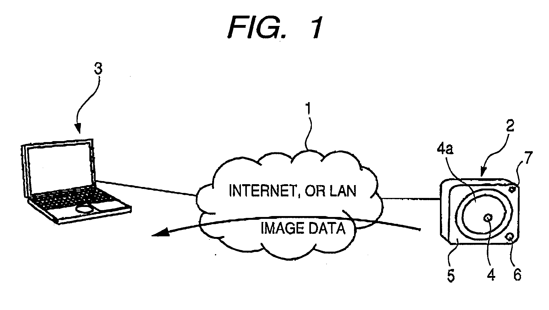
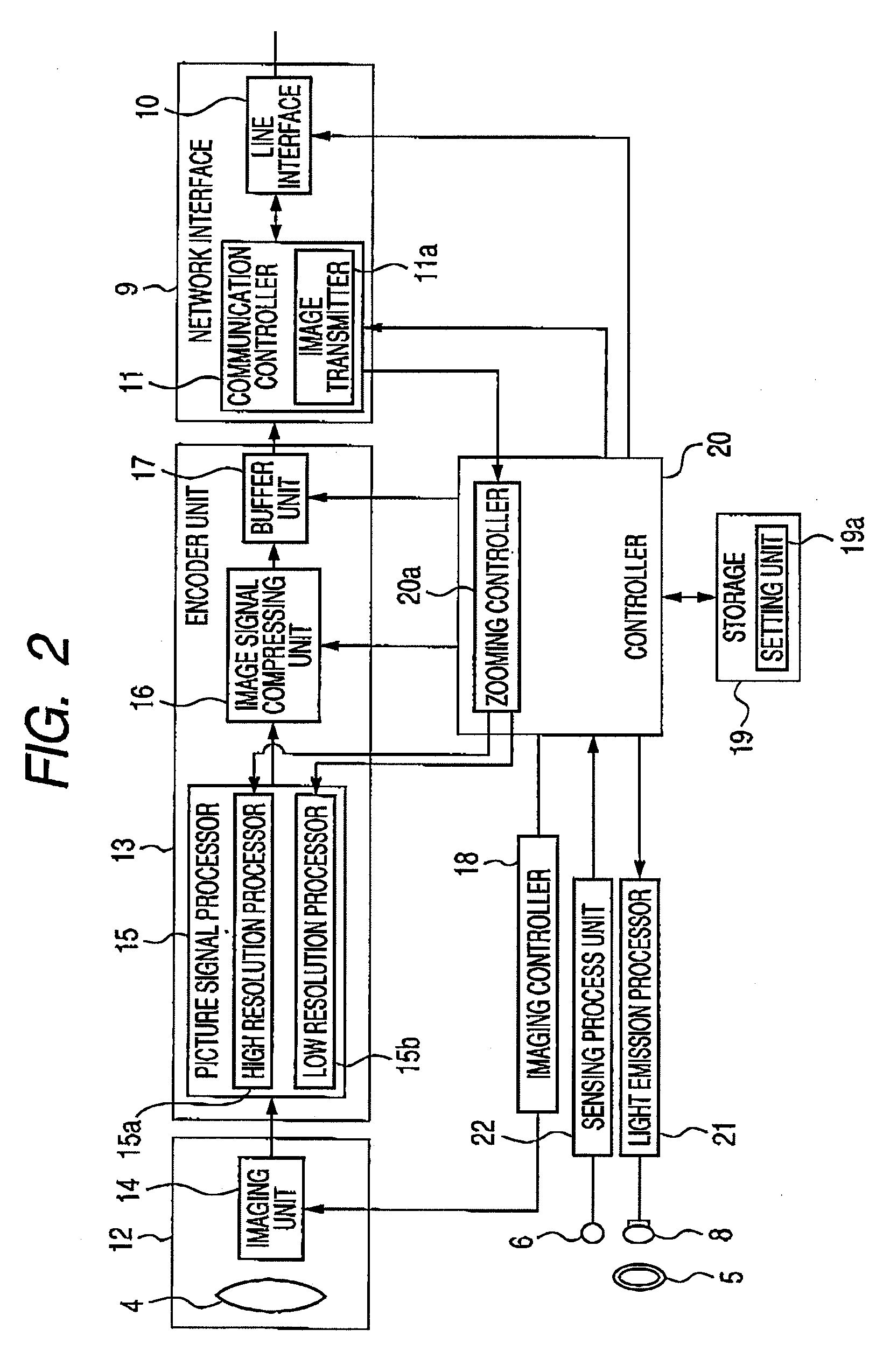
[0027]FIG. 1 is a network structural diagram of a network camera system according to an embodiment 1 of the present invention. FIG. 2 is a structural diagram of a network camera in the embodiment 1 of the present invention. FIG. 3 is a structural diagram of a terminal apparatus according to the embodiment 1 of the present invention. FIG. 4 is an explanatory diagram for explaining display changes of the terminal apparatus in the embodiment 1 of the present invention. FIG. 5 is an explanatory diagram for explaining a sequential operation when the terminal apparatus according to the embodiment 1 of the present invention is connected to the network camera. FIG. 6 is a flow chart for describing image dis...

embodiment 2

[0075]Next, a description is made of a network camera 2 according to an embodiment 2 of the present invention. The embodiment 2 is featured by utilizing a panning operation and a tilting operation by the pan / tilt charging unit 4a in addition to the above-described panning process operation and tilting process operation of the embodiment 1. It should be understood that since an arrangement of the embodiment 2 is identical to the arrangement of the embodiment 1, the same reference numerals indicate the same structural elements, and therefore, explanations thereof are omitted in this embodiment 2. Also, in the embodiment 2, FIG. 1 to FIG. 8 are used as references.

[0076]FIG. 9A is an explanatory diagram for explaining an image display in the case that an image area processed based upon the panning process operation and the tilting process operation of the terminal apparatus employed in the embodiment 2 of the present invention is disposed within a display area. FIG. 9B is an explanatory...


PUM


Abstract

A terminal apparatus displays an enlarge-processed image based upon an image having predetermined resolution while an image having high resolution is acquired, and switches the displayed image to display an image having the high resolution when the acquiring operation of the image having the high resolution is accomplished. The terminal apparatus can performs display operations based upon a panning process operation and a tilting process operation in addition to the enlarging process operation.

Description

BACKGROUND[0001]The present invention is related to a terminal apparatus for displaying an imaged obtained by a network camera, a method of controlling the terminal apparatus and a computer readable recoding medium.[0002]Recently, image distributing apparatuses have been widely popularized which distribute images when these image distributing apparatuses are accessed via IP networks from a large number of terminal apparatuses. Among these image distributing apparatuses, network cameras on which camera apparatuses are mounted have been widely popularized. Network cameras transmit images imaged by these network cameras to the respective terminal apparatuses, and in a certain case, also transmit voice to these terminal apparatuses by using microphones and speakers, while Web servers are communicated via the IP networks with Web browsers of terminal apparatuses such as personal computers by using, for example, the protocol of HTTP.[0003]In other words, when the Web browsers of the termi...

Claims


Application Information

Patent Timeline
IPC IPC(8): H04N7/14
CPCG06T3/40H04N5/23203H04N2201/0084H04N2101/00H04N2201/0039H04N7/18H04N23/66H04N5/2628H04N7/183
Inventor ARIMA, YUUJINAGAO, HIDEAKI
Owner PANASONIC I PRO SENSING SOLUTIONS CO LTD
Why Eureka
Try Eureka