Single polarization fiber and method of evaluating fiber cutoff wavelengths using optical time domain reflectometry

a single polarization fiber and optical time domain technology, applied in the field of single polarization fibers, can solve the problems of difficult to predict the precise length of the fiber segment, the measurement technique is destructive, and the inability to screen the cutoff wavelength of an entire length of fiber with the destructive measurement method

Inactive Publication Date: 2007-07-19
CORNING INC
View PDF4 Cites 14 Cited by
  • Summary
  • Abstract
  • Description
  • Claims
  • Application Information

AI Technical Summary

Benefits of technology

[0015] One advantage of the present method is that it can be incorporated in the fiber manufacturing process by providing online monitoring of the single polarization window during the fiber draw process.

Problems solved by technology

Thus, variability fundamental mode cutoff wavelengths within the length of the same fiber makes it difficult to predict the precise length of the fiber segment that needs to be cut off from the long length of fiber to provide the fiber with the predetermined cutoff wavelengths.
This measurement technique is destructive because once cut of from the rest of the fiber, the measured section fiber is usually discarded.
Unfortunately, screening fiber cutoff wavelengths on an entire length of fiber can not be done with the destructive measurement method.
Thus, acceptable cutoff wavelengths measured on the fiber segment does not guarantee that the rest of the fiber has acceptable cutoff wavelengths.
It is very difficult to make a fiber preform and draw it into a standard fiber diameter such as 125 μm with a single polarization window right on target.
However, a practical preform has always small random variations, which move the single polarization window significantly.
As a result, the average yield of targeted single polarization fibers can be very low.

Method used


Image

  • Single polarization fiber and method of evaluating fiber cutoff wavelengths using optical time domain reflectometry
  • Single polarization fiber and method of evaluating fiber cutoff wavelengths using optical time domain reflectometry
  • Single polarization fiber and method of evaluating fiber cutoff wavelengths using optical time domain reflectometry

Examples


first embodiment

of the Present Invention

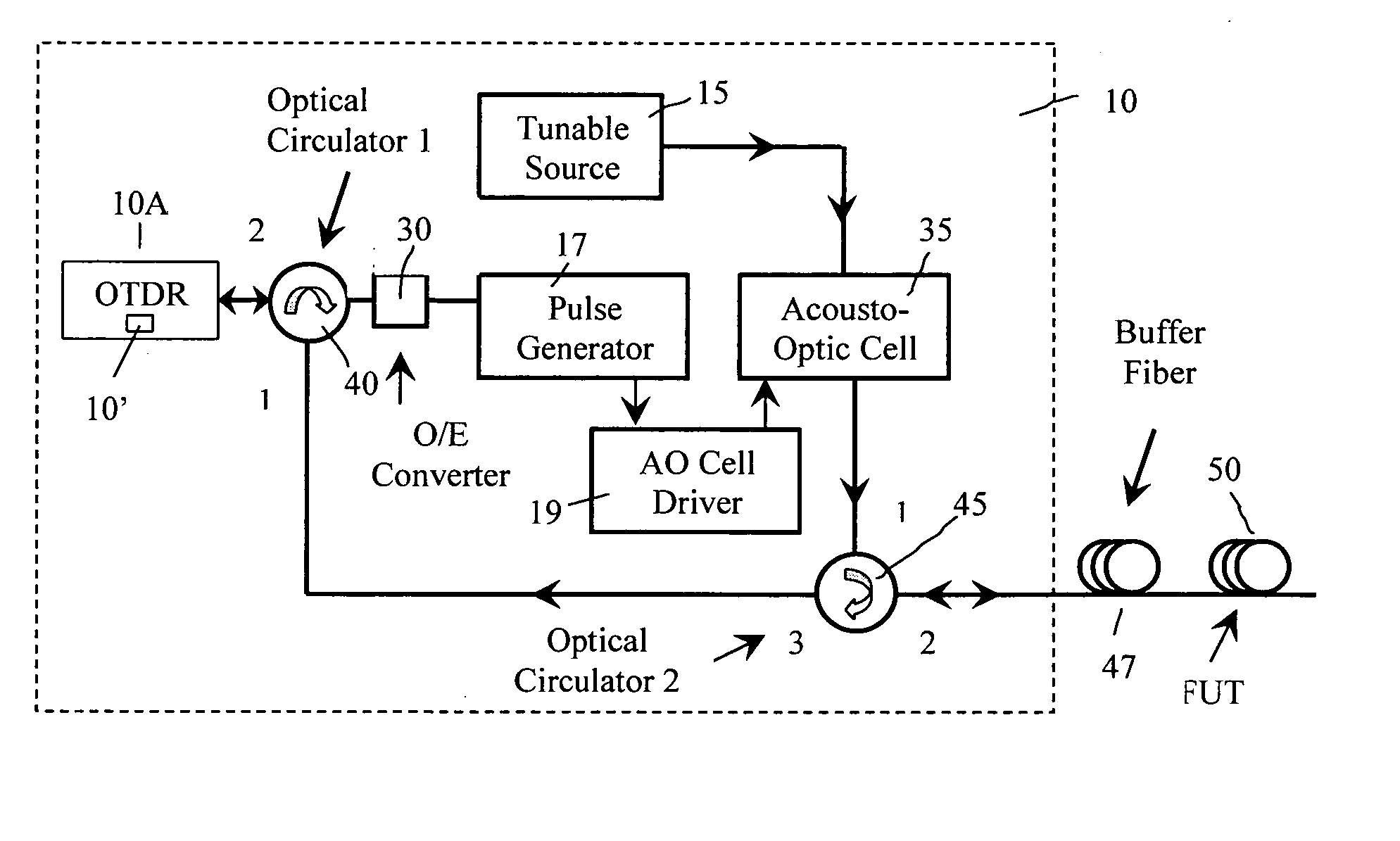
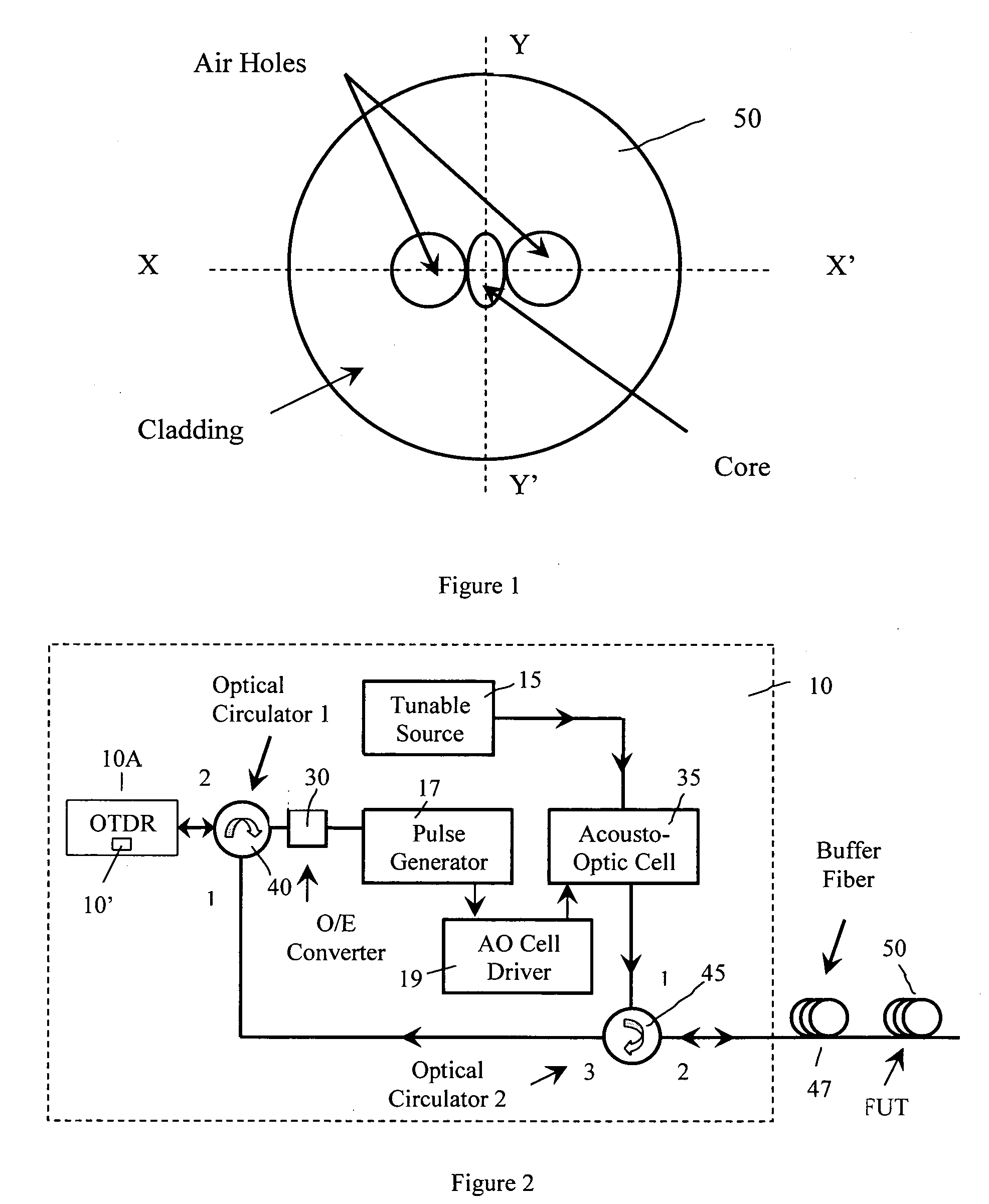
[0049] In this embodiment, the method of measuring the fundamental mode cutoff of the single polarization fiber is achieved by using a tunable OTDR device 10 (see FIG. 2). Tunable OTDR device 10 is an OTDR device that can run OTDR operation at different wavelength (tunable wavelength) within a specified wavelength range. Tunable OTDR devices are not commercially available. In order to gain the wavelength tunability, we modify a commercial OTDR device 10A to produce a tunable OTDR device 10. The schematic illustration of one embodiment of the tunable OTDR device 10 is shown in FIG. 2, which includes a commercial OTDR device 10A that operated at a fixed wavelength of 1550 nm. To gain the wavelength tunability, we utilized a tunable wavelength light source 15, which outputs continuous wave (CW) light at a specified wavelength. This light will then be fed to a modulator, for example an acousto-optical cell, which provides a “chopping” action to create pulses of l...

second embodiment

of the Present Invention

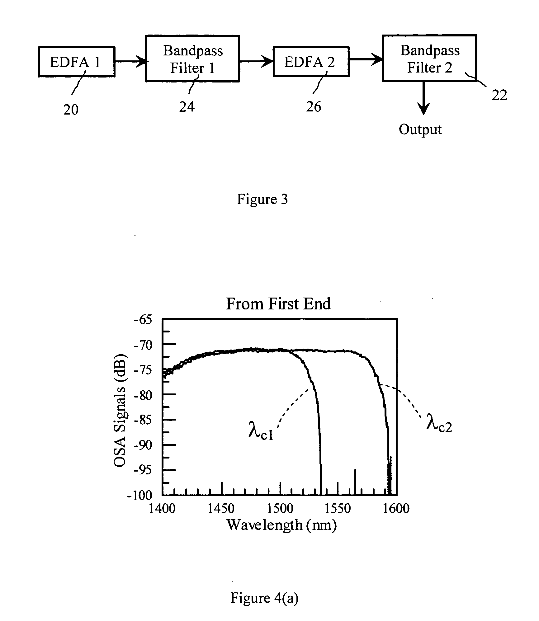
[0056] In the above embodiment, we have measured the wavelength of cutoff 2 wavelength (λc2) as a function of the fiber position, and have been able to select the specific fiber of interest. With some modification to the above measurement method, we can measure directly the wavelengths corresponding to cutoff 1 (λc1). In order to achieve this goal, we modify the tunable OTDR device 10 illustrated in FIG. 2 by utilizing a rotatable polarizer 70 in the tunable OTDR device 10 as now illustrated in FIG. 7. The polarizer axis should be aligned with the fiber's birefringent (i.e., polarization) axis associated with the polarization mode of the shorter cutoff wavelengths λc1, so that no light associated with the polarization mode of longer cutoff wavelength λc2 is launched into the optical fiber 50. By properly aligning the polarizer orientation, we gain sole access to the polarization mode with longer cutoff wavelength λc2. The location (P1, not shown) of sharp dro...

third embodiment

of the Present Invention

[0059] The distributed cutoff measurement method can be used in conjunction with a preform that has a tapered core, to improve the yield of manufacturing of the single polarization fibers. First, we obtain or manufacture a fiber preform that has a predetermined taper of the core size. FIG. 8a shows a schematic cross-section of an exemplary preform, where d1 and d2 are average core diameters of the two ends, and L is the length of preform. In this example, the taper has linear change along the preform. Such a tapered preform is formed utilizing the following method of manufacturing. First, a core cane 100, as shown in FIG. 11, is provided having the proper germania-doped core delta, Δ1, in the central core 104a of between about 0.5-2.5%, and an annular region 102a doped with fluorine surrounding the core 104a having a delta, Δ2, of between about −0.05 to −0.75%. The core cane 100 was preferably 1 meter long and about 42 mm in diameter. Grooves 106 are then gro...


PUM

PropertyMeasurementUnit
cutoff wavelengthaaaaaaaaaa
diameteraaaaaaaaaa
pulse widthsaaaaaaaaaa

Abstract

A method for measuring fundamental mode cutoff wavelength of single polarization fiber comprising: (i) launching pulsed light of at least one wavelength λi into one end of the single polarization fiber; (ii) measuring backscattered light intensity corresponding to said wavelength to obtain the backscattered light intensity as a function of fiber position, wherein the backscattered light propagates through the same end of the fiber; and (iii) determining at least one cutoff wavelength and the corresponding position within said fiber for the cutoff wavelength, based on a specified threshold light intensity level.

Description

BACKGROUND OF THE INVENTION [0001] 1. Field of the Invention [0002] The present invention relates generally to optical fibers, and particularly to a method for distributed measurement of fundamental mode cutoff wavelengths in optical fibers. This method is especially suitable for measuring fundamental mode cutoff wavelengths of optical fibers which exhibit single polarization characteristics. [0003] 2. Technical Background [0004] Optical fiber has become a favorite medium for telecommunications due to its high capacity and immunity to electrical noise. Single polarization optical fibers are useful for ultra-high speed transmission systems or for use as a coupler fiber for use with, and connection to, optical components (lasers, EDFAs, optical instruments, interferometric sensors, gyroscopes, etc.). Single polarization fibers (SPFs) propagate light in one, and only one, of two orthogonally polarized polarizations while suppressing the other polarization by increasing its transmission...

Claims


Application Information

Patent Timeline
Patent Type & Authority Applications(United States)
IPC IPC(8): G02B6/00
CPCC03B37/0124G01M11/3181C03B2203/14C03B37/07Y02P40/57
Inventor CHEN, XINEVANS, ALAN FRANKKOH, JOOHYUNLI, MING-JUNNOLAN, DANIEL ALOYSIUS
Owner CORNING INC
Why Eureka
Try Eureka