Golf tee connector

Inactive Publication Date: 2007-07-19
LIPIDAROV PETER
View PDF8 Cites 10 Cited by
  • Summary
  • Abstract
  • Description
  • Claims
  • Application Information

AI Technical Summary

Benefits of technology

[0006] In accordance with the present invention a golf tee connector that allows a Range Pro™ golf tee application Ser. No. 11/199

Problems solved by technology

No resistance from the mat means no tearing of the Range Pro™ golf tee application #11/199,540 this is because this tee flexes in the direction that it is struck with a golf club, not like the conventional rubber tee that comes up from the bottom of the mat

Method used


Image

  • Golf tee connector
  • Golf tee connector
  • Golf tee connector

Examples


Embodiment Construction

—PREFERRED EMBODIMENTS

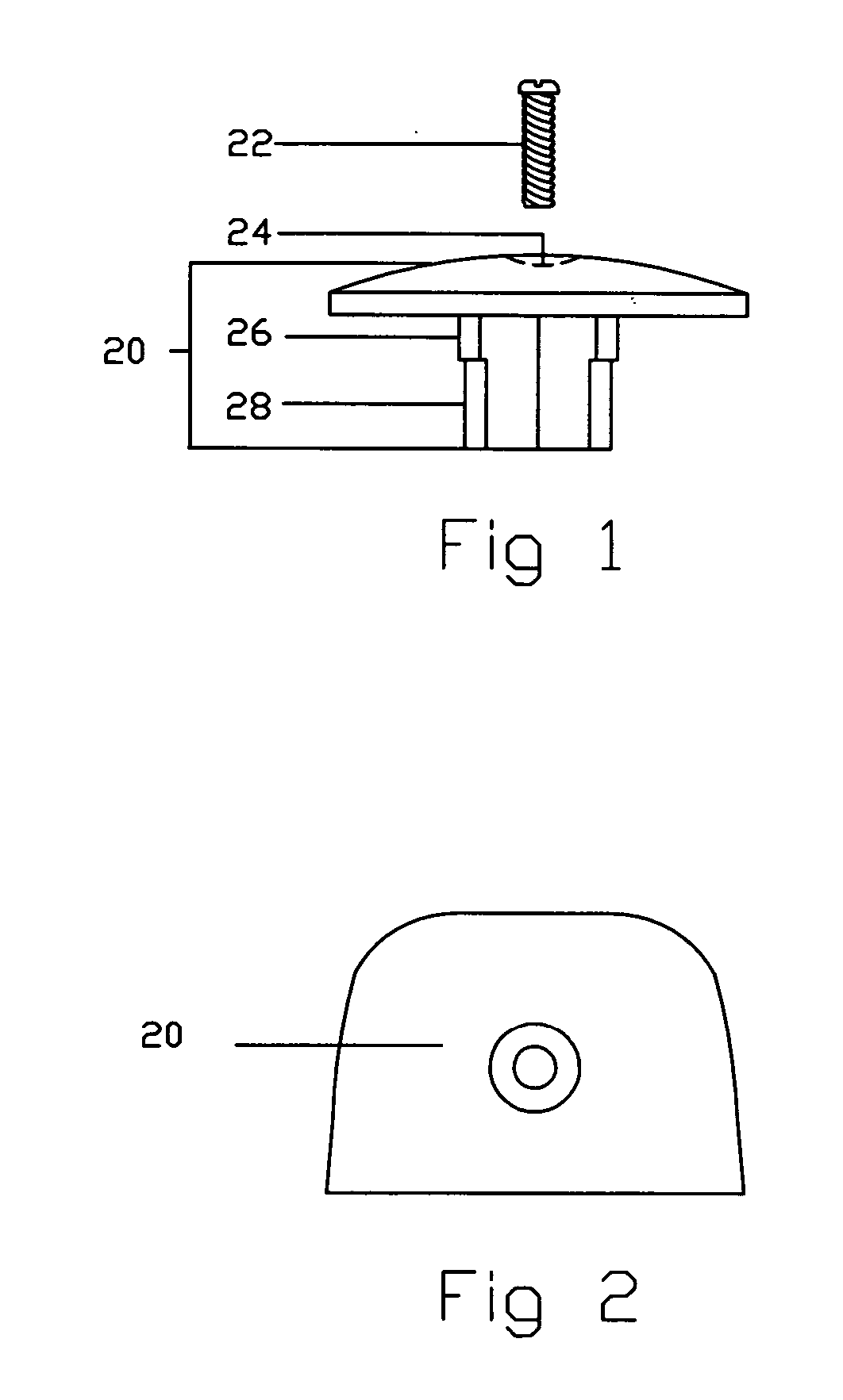
[0042] A preferred embodiment of the golf tee connector of the present invention is illustrated as a side view in FIG. 1 of a top of connector 20 that has a fitted shape 26 on it to hold a Range Pro™ golf tee application Ser. No. 11 / 199,540. Under the fitted shape 26 is a smaller fitted shape 28 this will interlock to the bottom connector. There is a counter sunk hole 24 that allows a bolt 22 to sink below the top out of sight and the way. The bolt 22 will attach and hold together the bottom and top of the connector.

[0043]FIG. 2 illustrates a top view of the top of connector 20.

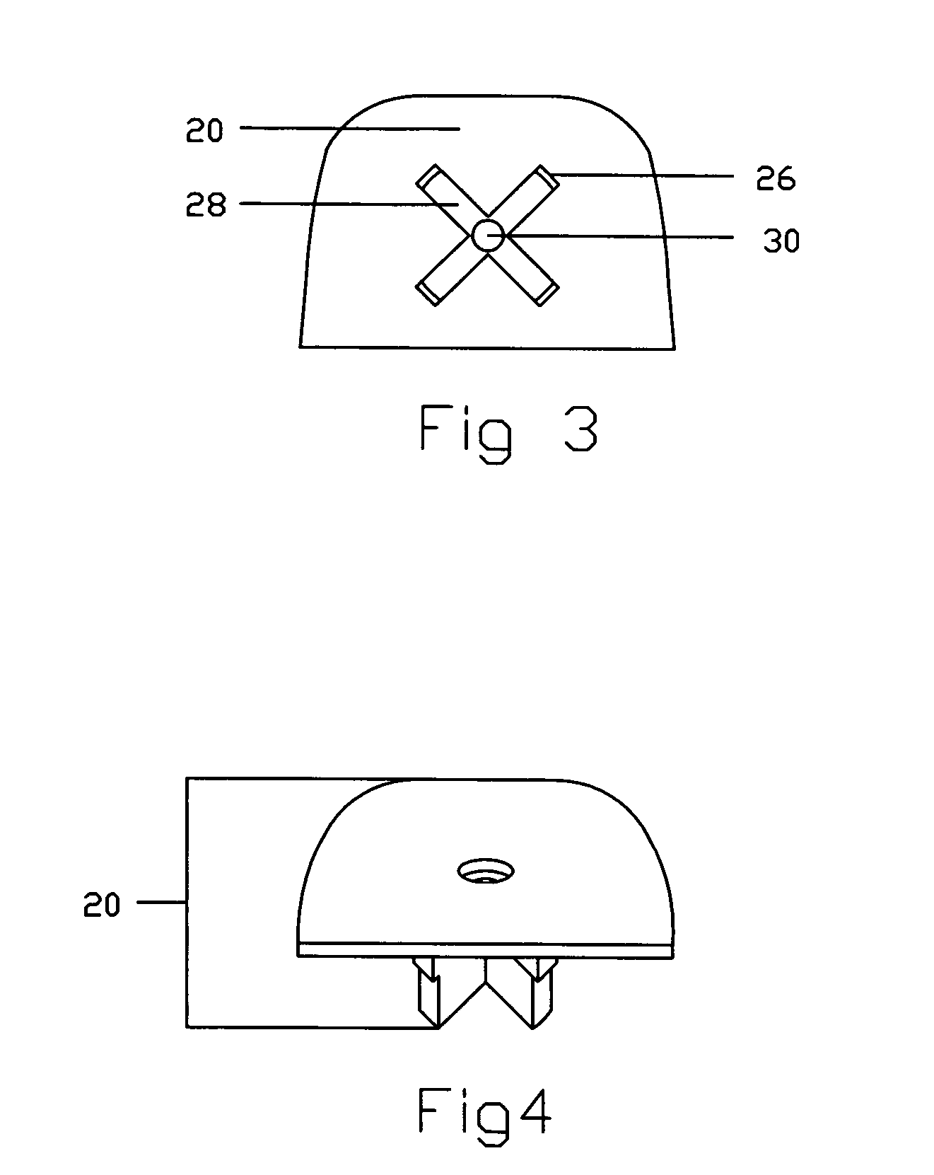
[0044]FIG. 3 illustrates a bottom view of the top of connector 20 showing the fitted shape 26 and the smaller fitted shape 28 in the center of both fitted shapes there is a through hole 30 which allows a bolt to continue through the top of connector 20.

[0045]FIG. 4 illustrates a perspective view of the top of connector 20.

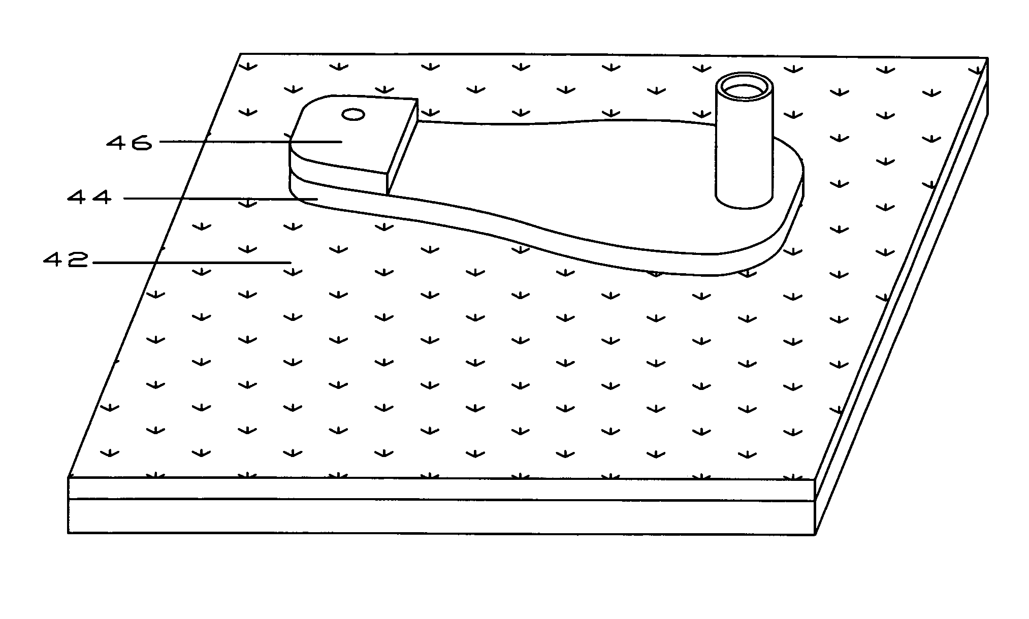
[0046]FIG. 5 illustrates a exploded view of the top of connect...


PUM


Abstract

A golf tee connector (46) designed for golf practice. Said connector allows a Range Pro™ golf tee application Ser. No. 11/199,540-(44) to connect to a mat, creating a connection that helps save time and money on the costly replacement of golf tees that come up from the bottom of the mat and by allowing the Range Pro™ golf tee application Ser. No. 11/199,540-(44) to connect to a mat brings that state of the art flexibility that Range Pro™ golf tee application Ser. No. 11/199,540-(44) is known for with no resistance from the mat, making a long life tee useable on a driving range mat.

Description

BACKGROUND OF THE INVENTION—FIELD OF INVENTION [0001] This invention relates to golf tees, more particularly to a golf tee connector that allows a Range Pro™ golf tee Application Ser. No. 11 / 199,540 to connect to a driving range mat.BACKGROUND OF THE INVENTION—PRIOR ART [0002] No prior art available BACKGROUND OF THE INVENTION—OBJECTS AND ADVANTAGES [0003] The present invention is to provide a connection between the Range Pro™ golf tee application Ser. No. 11 / 199,540 and a golf range mat. [0004] A current object and advantage is this connection allows a flexible tee to attach to a mat in turn allowing a golf driving range owner to use this connection to place a flexible tee on their mats saving them time and daily replacement of the conventional rubber tee that comes up from the bottom of a mat, that is currently being used. This connection saves time because a golf range owner will not have to replace the tee that comes up through the mat as often because with this connection there...

Claims


Application Information

Patent Timeline
IPC IPC(8): A63B57/00
CPCA63B57/0018A63B71/023A63B69/3623A63B57/10
Inventor LIPIDAROV, PETER
Owner LIPIDAROV PETER
Why Eureka
Try Eureka