Super stirrup

Inactive Publication Date: 2007-07-26
HUSSEY CHARLES
View PDF22 Cites 3 Cited by
  • Summary
  • Abstract
  • Description
  • Claims
  • Application Information

AI Technical Summary

Benefits of technology

[0011] When comparing the present invention to the prior-art, the prior-art has various limitations and does not serve to achieve the primary purpose of the present invention which is to give the rider effective control, proper balancing support and ease in riding derived from using a stirrup which is configured and shaped to ensure firm footing, more comfort, correct foot placement, safety, durability, and effective riding.
[0012] In particular, the present invention comprises an additional bar as part of the frame of the stirrup, namely an “extra support bar” serving to support the rider's third toe to the big toe and running at an angle from the platform base to the stirrup hole. The platform base is shaped in the form of the forefoot or the forward portion nearest the toes of a foot which is where the rider positions the toe box of his riding boots. This “sole-shaped” platform base gives extra foot space and comfort to support the first to third toes and toe box of the boot thus enhancing the rider's balance.
[0013] The widened platform base also has grooves on the surface which run counter to the direction of the movement of the boots to allow for better grip. The widened base also aims at preventing shin, Achilles tendon, and sole of foot soreness commonly associated with the continued use of the existing stirrups. The stirrup strap hole is positioned at an angle just above the center of the rider's boot to facilitate necessary and skillful maneuvers of the rider. The angle of the hole corresponds with the saddle buckle which is angled by virtue of how the saddle rests on the horse. In traditional stirrups, the stirrup strap hole is not angled; hence, over the course of time, the saddle buckle tends to get worn on one side from riding. The angled stirrup strap hole in the present invention provides for a smoother ride as its angle corresponds to the angle and movement of the saddle bucket during a ride.
[0014] The presence and position of the extra support bar, the widened and grooved platform base and the shape and angle of the main stirrup bar give the rider better balance support and ensure firm footing, correct foot placement, correct riding style and ease of riding. The present invention enables the rider to use less energy in balancing his / her body weight, and the present invention also serves to minimize accidents and injuries. Additionally, although specifically designed based on the sport of horse-racing, the present invention can also be adapted for use in related equestrian activities and sports.

Problems solved by technology

In traditional stirrups, the stirrup strap hole is not angled; hence, over the course of time, the saddle buckle tends to get worn on one side from riding.

Method used


Image

  • Super stirrup
  • Super stirrup
  • Super stirrup

Examples


Embodiment Construction

[0029] In the discussion of the FIGURES, the same reference numerals will be used throughout to refer to the same or similar components.

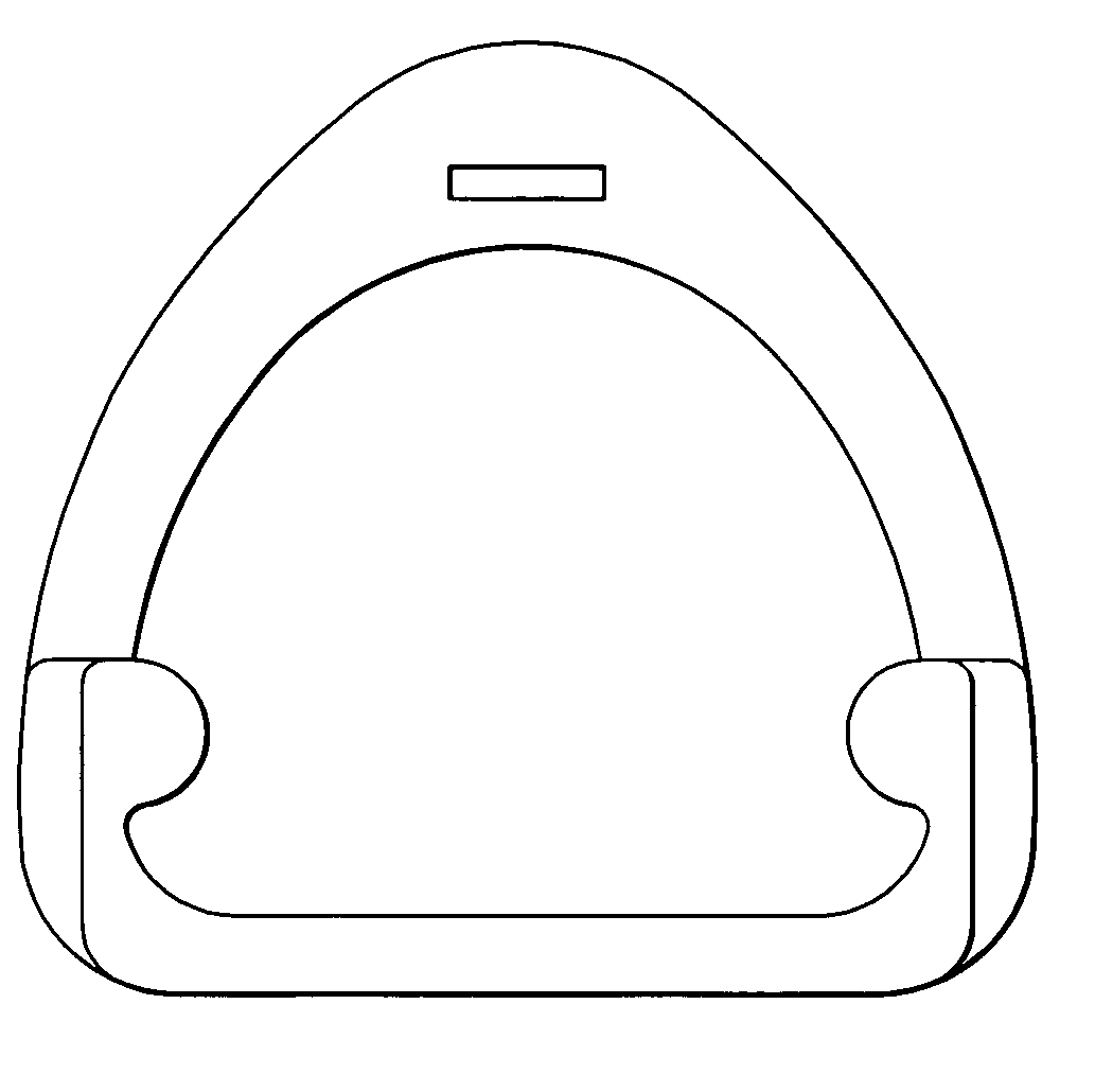
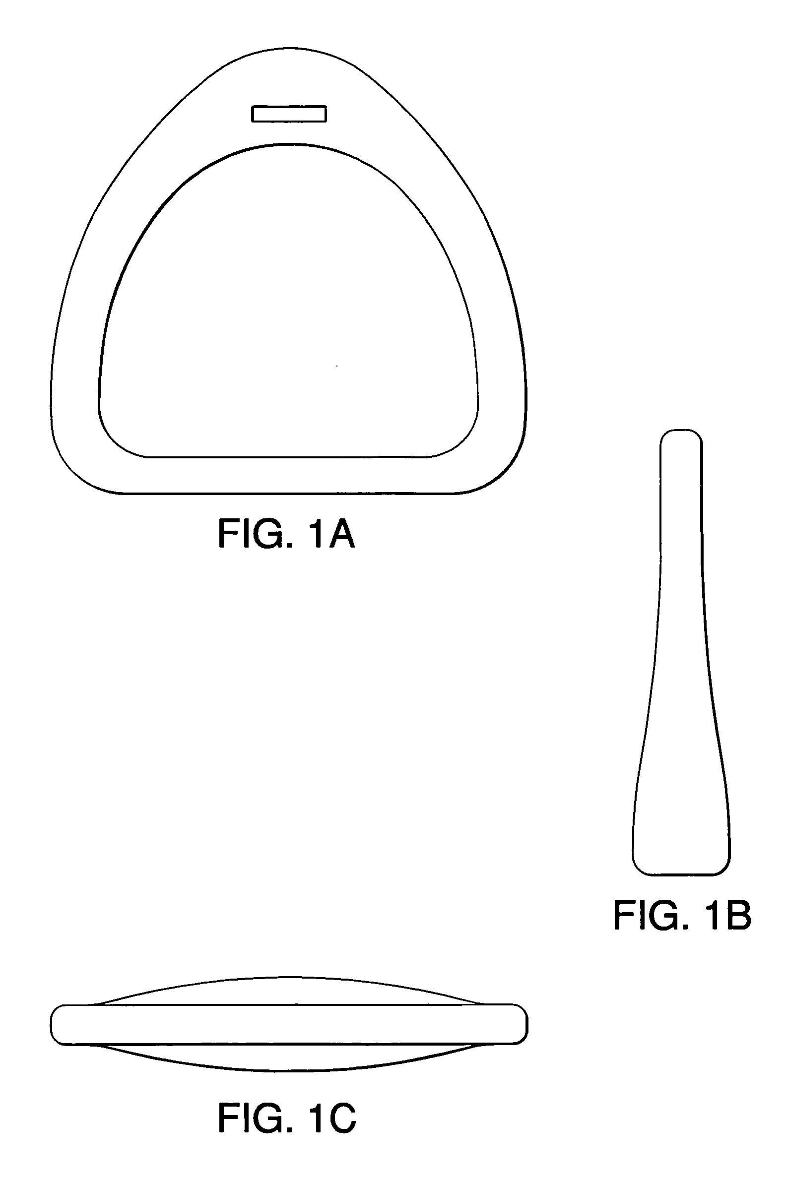
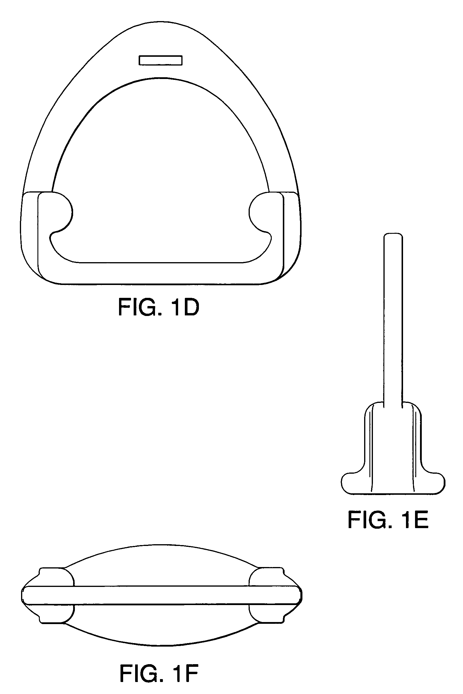
[0030] Referring to FIGS. 2-9 of the drawings, the reference numeral 100 generally designates an improved stirrup. As can be seen in FIG. 2-9, the stirrup comprises the following: [0031] a sole-shaped platform base 102, which is grooved; [0032] three support bars or members: [0033] the first support bar 104 being the main support bar attached to the rear of the platform base; [0034] the second support bar 106 being attached to the front side of the platform base in the region of the rider's big toe; and [0035] the third support bar 108 being an extra support bar attached to the front side of the platform base in the region of the rider's third toe; and [0036] an angled stirrup strap hole 110.

[0037] The platform base 102 is shaped in the form of the forefoot or the forward portion nearest the toes of a foot. Base 102 is the platform on which the ri...


PUM


Abstract

Until recently, stirrups have not provided adequate support for a rider allowing for ease of balance when riding, and especially while racing. The super stirrup described herein provides a stable platform or base accompanied by a number of support bars that allow the rider to rest and reposition his or her weight easily. Thus, the super stirrup improves the performance of a rider in both leisure and sport riding.

Description

CLAIM OF PRIORITY [0001] This application claims priority from Jamaican Patent Application No. 18 / 1 / 4417 entitled “SUPER STIRRUP” filed on behalf of Charles Hussey, on Jan. 26, 2006, which is hereby incorporated by reference for all purposes. Technical Field [0002] The invention relates generally to a stirrup and, more particularly, to an improved form of stirrup iron for use in horse racing and related activities, including training. BACKGROUND [0003] Beginning with a simple loop or ring with a flat bottom to create a footrest for the rider and to enable him / her to mount an animal, stirrups have been around for centuries. [0004] The modern-day stirrup iron for horse-riding essentially comprises a horizontal base or flat bottom, joined by two bars on either side of the base running vertically and being angled towards the top where there is a stirrup strap hole. These components are described herein as the frame of the stirrup. See FIGS. 1A-1C for the basic stirrup frame. The stirrup...

Claims


Application Information

Patent Timeline
IPC IPC(8): B68C3/00
CPCB68C3/00
Inventor HUSSEY, CHARLES
Owner HUSSEY CHARLES
Why Eureka
Try Eureka