Winding apparatus for waveguide prototype mould and waveguide manufacturing method

Inactive Publication Date: 2016-05-26
METAL INDS RES & DEV CENT
View PDF0 Cites 1 Cited by
  • Summary
  • Abstract
  • Description
  • Claims
  • Application Information

AI Technical Summary

Benefits of technology

[0010]The present invention has the following features: because a growing direction of the electrotyped layer can be precisely controlled, the present invention is applicable to high-precision prototypes (of which the tolerance is less than minus or plus 1 μm). Because the waveguide prototype is made by precisely machining an alloy with a low melting point, the present invention does not need any additional conductive treatment. With non-conductive treatment on partial surface of the waveguide prototype of the present

Problems solved by technology

However, in the foregoing procedures, it cannot be controlled that partial surface of the waveguide prototype 10 is conductive or non-conductive, and a uniform and stable electrotyped layer 13 cannot be formed between specific machined wa

Method used


Image

  • Winding apparatus for waveguide prototype mould and waveguide manufacturing method
  • Winding apparatus for waveguide prototype mould and waveguide manufacturing method
  • Winding apparatus for waveguide prototype mould and waveguide manufacturing method

Examples


Example

[0024]Preferred embodiments of the present invention are described in detail below with reference to the accompanying drawings. All the accompanying drawings are simplified schematic figures, which merely describe the basic structure of the present invention in a schematic manner. Therefore, only elements related to the present invention are shown in the drawings, and the elements are not displayed according to the quantity, shape, or dimensional proportion during implementation. During practical implementation, there are options for design of the specifications, and the element arrangement may be more complex.

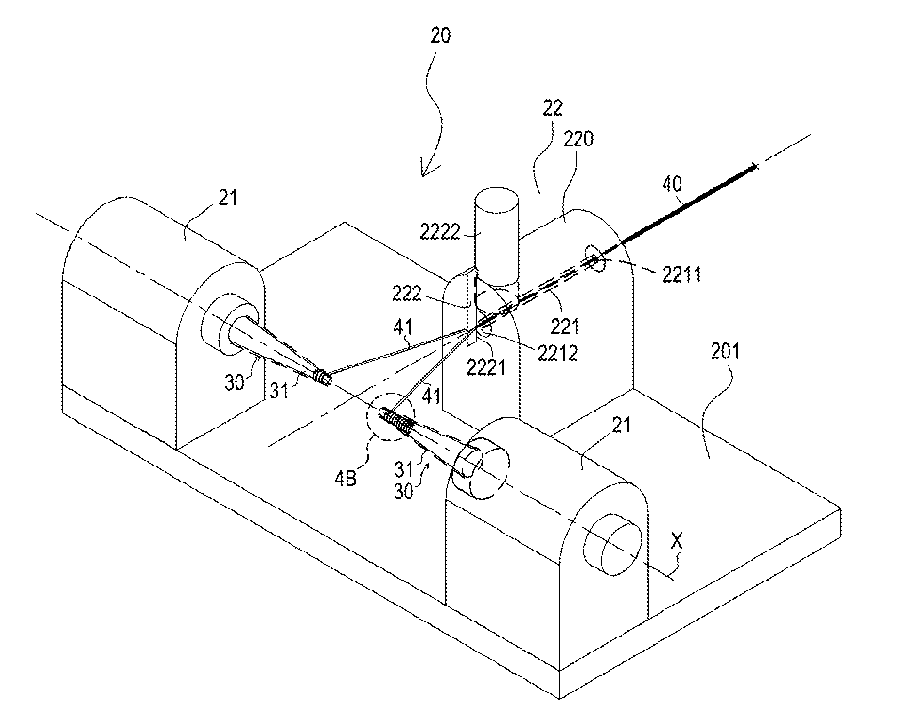
[0025]First, refer to FIG. 4A and FIG. 4B. This embodiment is a winding apparatus 20 for a waveguide (or referred to as corrugated horn) prototype mold 50; the waveguide prototype mould 50 is formed by treating a waveguide prototype 30 by the winding apparatus 20. The waveguide prototype 30 includes a rod body 31; a surface of the rod body 31 is periodically provided with radi...


PUM

PropertyMeasurementUnit
Lengthaaaaaaaaaa
Diameteraaaaaaaaaa
Diameteraaaaaaaaaa

Abstract

A wiring apparatus includes a substrate, two winding modules, and an axial wire dividing module. The two winding modules are disposed on the substrate. Each winding module includes a clamping mechanism with a chuck, a rotary mechanism having a rotation driving unit driving the chuck; and a reciprocating mechanism with a rail-slider assembly, the rotation driving unit connected to the slider. The axial wire dividing module is disposed on the substrate and located between the two winding modules with a wire supply channel provided with a wire inlet and a wire outlet. The wire outlet is provided with a cutter aligned with the center of the wire supply channel, and a cutting edge of the cutter faces the wire inlet; a waveguide prototype mould is formed by dividing a wire in real time and winding wires in grooves of a waveguide prototype.

Description

BACKGROUND[0001]1. Technical Field[0002]The present invention relates to a winding apparatus for a waveguide prototype mould and a waveguide manufacturing method, and in particular, to an apparatus and a method that make a wire thinner and smaller by using a real-time wire dividing technology, wind and fasten wires in grooves between convex teeth of a high-precision waveguide prototype, and then manufacture a waveguide by using the waveguide prototype.[0003]2. Related Art[0004]Waveguides (also referred to as corrugated horns) are main components for microwave transmission, and can be applied to communications industries in the fields of satellites and outer space; waveguides have military applications such as radar detection and communications, and also have industrial and civilian applications such as microwave ovens (heating, drying, and defrosting), microwave extraction (extraction, purification, and environmental decontamination), microwave radars (such as speed measurement, dis...

Claims


Application Information

Patent Timeline
IPC IPC(8): C25D5/02C25D7/00B65H81/00C25D11/20
CPCC25D5/02B65H81/00C25D7/00C25D11/20H01P11/002C25D1/00C25D11/022B65H81/06
Inventor CHENG, SHENG-YUAN
Owner METAL INDS RES & DEV CENT
Why Eureka
Try Eureka