Automatic flow measuring device

a technology of automatic flow measurement and measuring device, which is applied in the direction of measurement device, volume/mass flow measurement, instruments, etc., can solve the problems of operator error in timing, lack of consistency, and inability to automatically measure or totalize flow

Inactive Publication Date: 2007-07-26
CONTROL & POWER SYST
View PDF2 Cites 8 Cited by
  • Summary
  • Abstract
  • Description
  • Claims
  • Application Information

AI Technical Summary

Benefits of technology

[0007] It is another object of the present invention to provide an automatic flow measuring...

Problems solved by technology

Inherently, the problems are operator error in the timing and a lack of consistency thereof.
Additionally, as a manual system there is no possibility of automatic ...

Method used


Image

  • Automatic flow measuring device
  • Automatic flow measuring device

Examples


Embodiment Construction

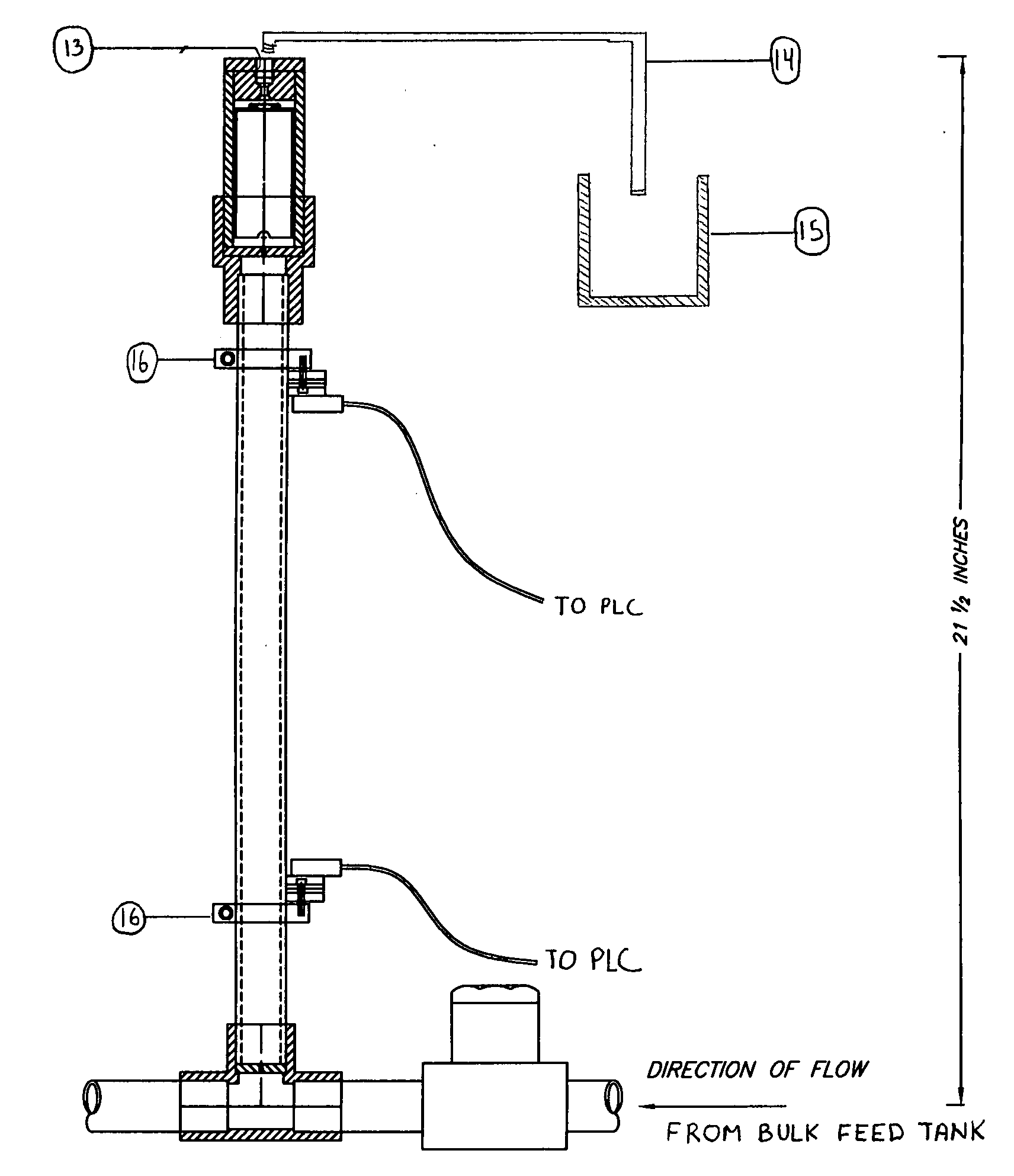
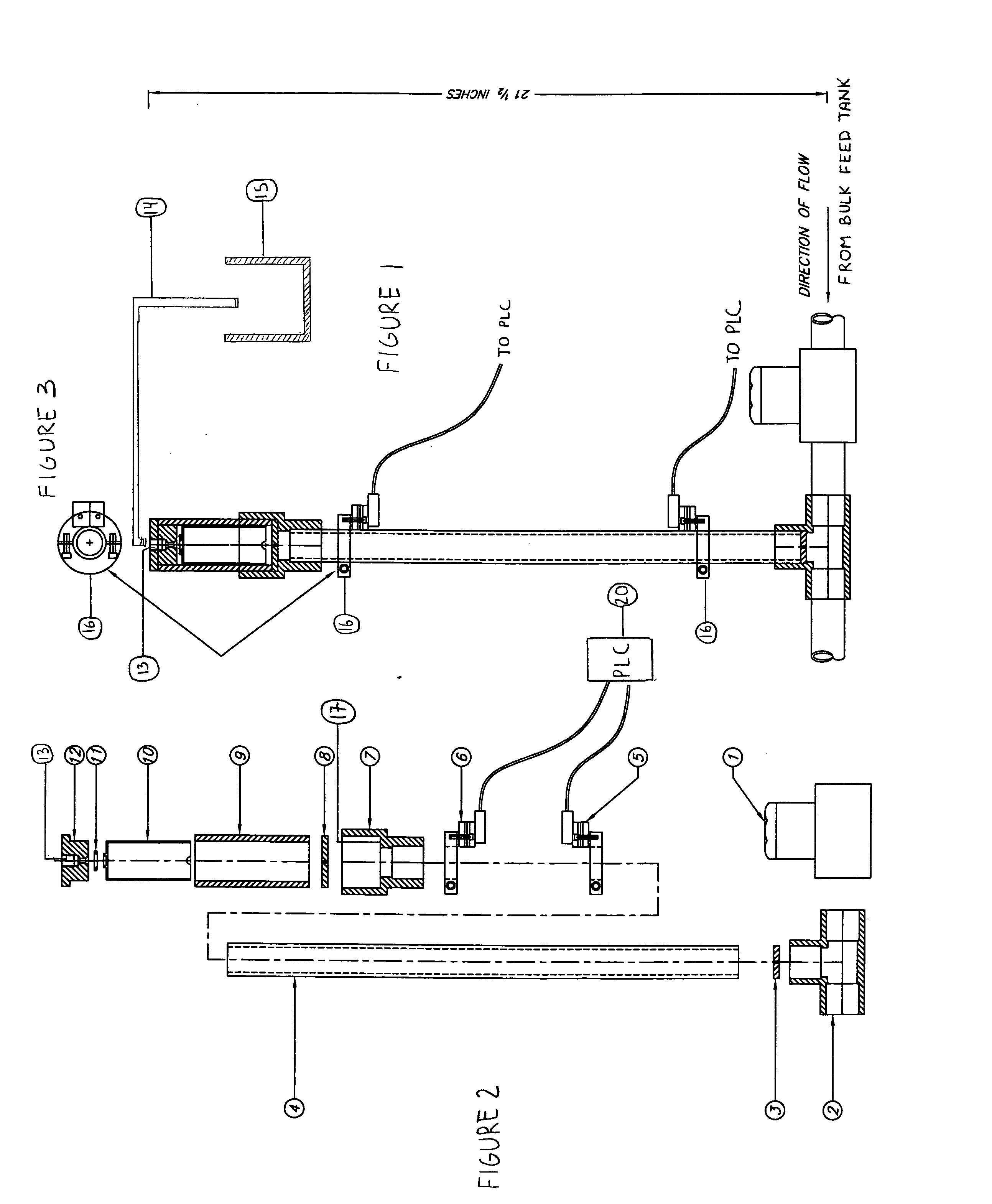
[0019]FIGS. 1, 2 and 3 of the drawing show an automatic flow measuring device formed in accordance with the present invention. Fluid flows in the direction indicated by the arrow depicted in FIG. 1. Fluid from a bulk feed tank (not shown) or other fluid source is provided to the input port of an automatically operated valve 1, such as a solenoid valve, whose output port is connected to the input port of a fluid diverter or tee connector 2. The tee connector 2 has a main flow output port and a diversion output port. The flow of fluid splits in the tee connector 2 as it is continuously pumped, and part of the flow diverts through the diversion output port, the remainder flowing through the main output port of the tee connector 2.

[0020] A measuring chamber 4, which is preferably defined by an elongated tubular or cylindrical structure with an axial bore formed therethrough, and which also has a sidewall which is preferably clear or transparent, either entirely or over portions thereof...


PUM


Abstract

An automatic flow measuring device is used in an industry where accuracy in dispensing of liquid is necessary. It is fully automatic in nature and is used with a PLC (programmable logic controller) to give the system intelligence and reporting capability. The automatic flow measuring device for measuring fluid flow includes an automatically operated valve, a tee connector operatively coupled to the automatically operated valve, an elongated member defining a measuring chamber coupled to the tee connector, at least a first fluid level sensor mounted on the elongated member at a first position thereon and a second fluid level sensor mounted on the elongated member at a second position thereon. The first and second sensors are preferably electronic and send signals to the PLC which opens and closes the automatically operated valve.

Description

CROSS REFERENCE TO RELATED APPLICATION [0001] This application is related to U.S. Provisional Application Ser. No. 60 / 740,717 filed on Nov. 30, 2005, and entitled “Automatic Flow Measuring Device”, the disclosure of which is incorporated herein by reference and on which priority is hereby claimed.BACKGROUND OF THE INVENTION [0002] 1. Field of the Invention [0003] The present invention relates to fluid flow measurement devices, and more particularly relates to fluid flow measurement devices employing a calibration cylinder. [0004] 2. Description of the Prior Art [0005] Traditionally, calibration cylinders are manual devices whereby an operator diverts the flow into a calibration tube and closes off a valve from the main flow causing the calibration cylinder to act as the main source of flow. Using a timing device, the operator notes the time it takes for the graduated calibration cylinder to empty and mathematically converts this time to a rate of flow. Inherently, the problems are o...

Claims


Application Information

Patent Timeline
IPC IPC(8): G01F5/00
CPCG01F25/0007G01F25/10
Inventor ZALITE, MARTIN W.MESMER, LARRY P.
Owner CONTROL & POWER SYST
Why Eureka
Try Eureka