Fluid control apparatus with heating apparatus

Inactive Publication Date: 2007-07-26
FUJIKIN INC
View PDF23 Cites 1 Cited by
  • Summary
  • Abstract
  • Description
  • Claims
  • Application Information

AI Technical Summary

Benefits of technology

[0010] In accordance with the structure mentioned above, an interval between the heat insu

Problems solved by technology

However, it is not possible to sufficiently bring the heater into close contact with a fluid control device main body or the like, only with an elastic force by the clips.
Accordingly, there is a case that a heating capacity comes short with respect to a required temperature, for example, a case that it is possible to heat to about 50° C. but it is not possible to heat to 80° C. or more.
Although a structure in which a silicone sponge is adhered as a heat insulating mat

Method used


Image

  • Fluid control apparatus with heating apparatus
  • Fluid control apparatus with heating apparatus
  • Fluid control apparatus with heating apparatus

Examples


Example

[0013] A description will be given below of an embodiment in accordance with the invention with reference to the accompanying drawings.

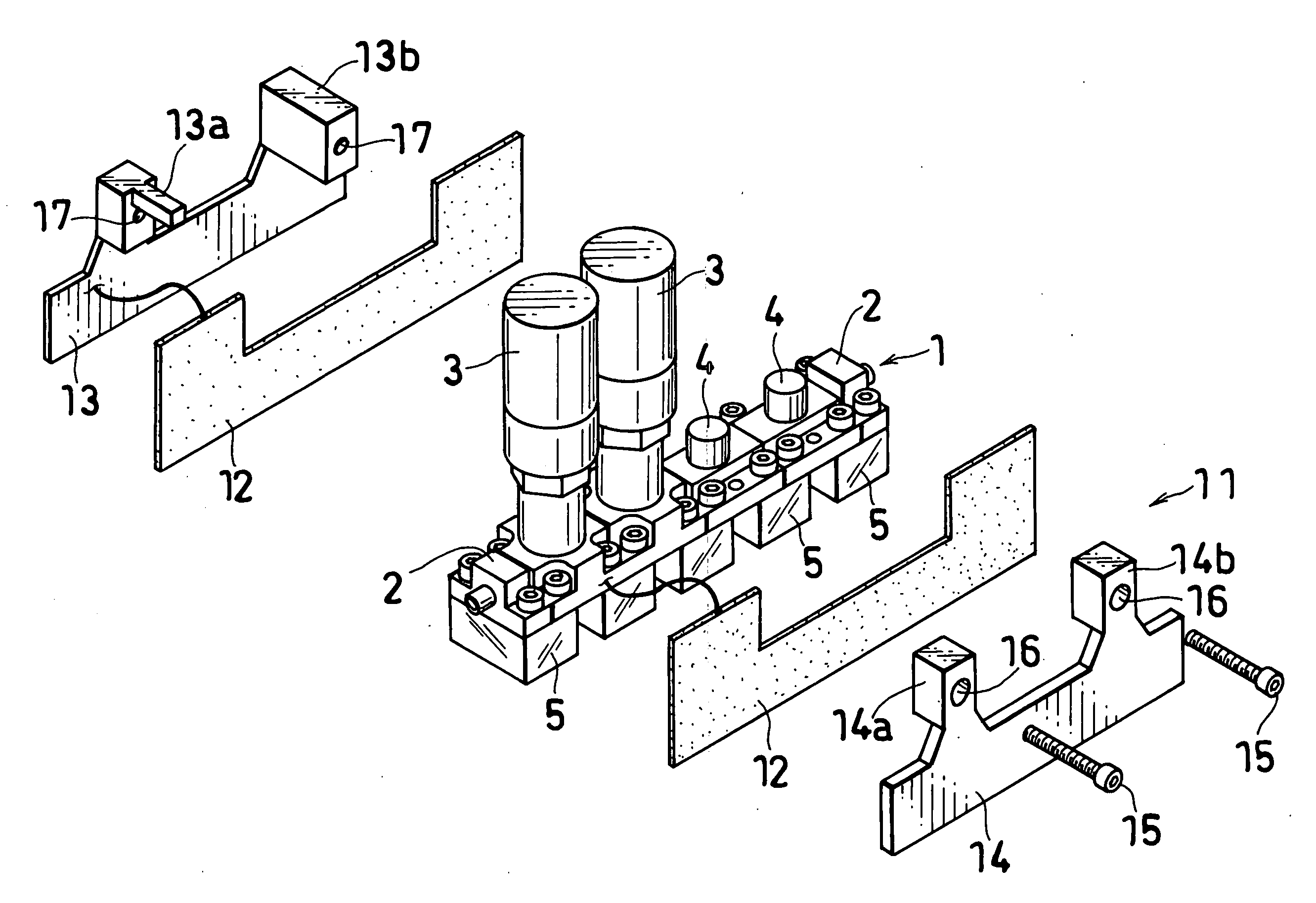
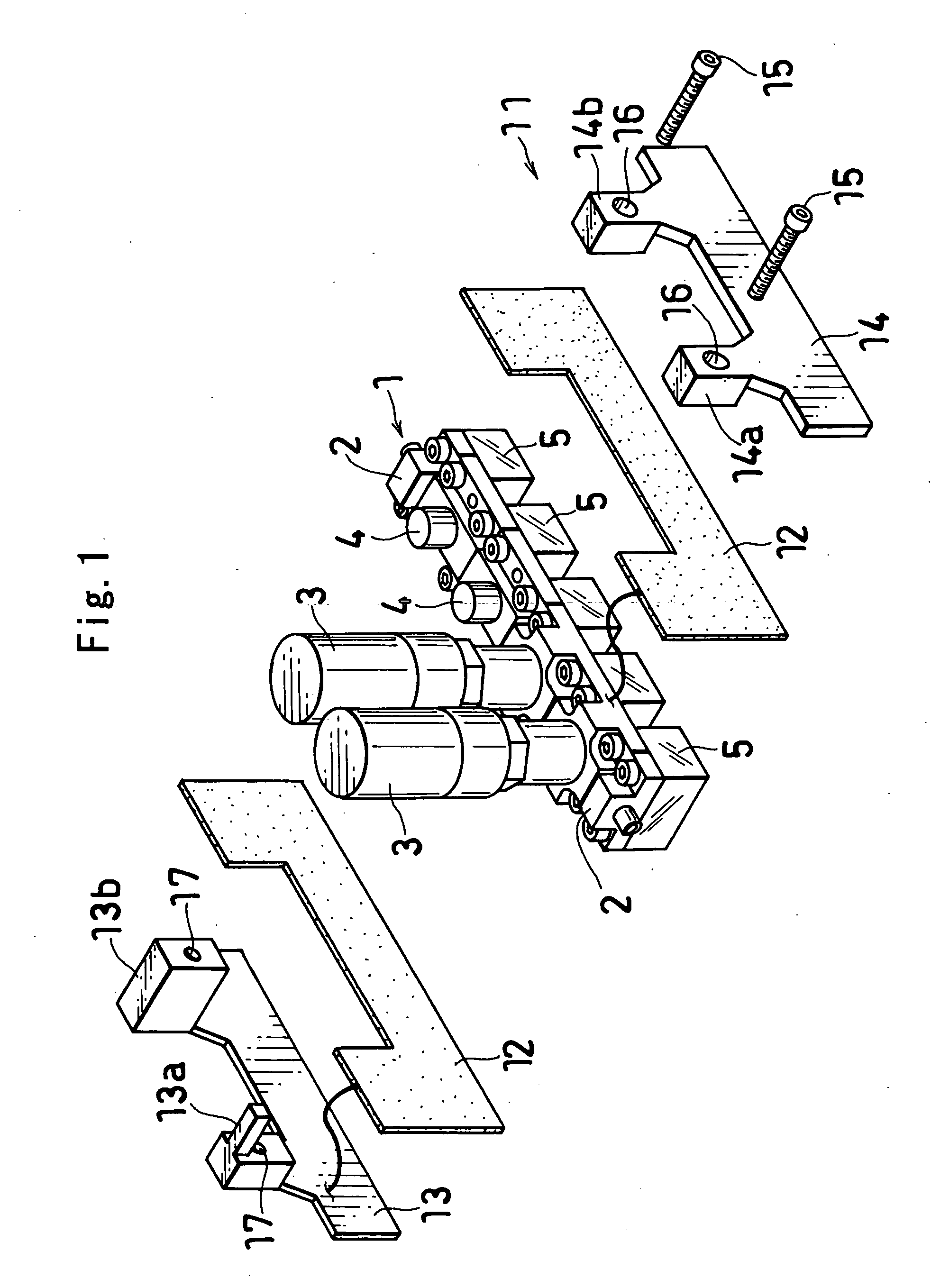
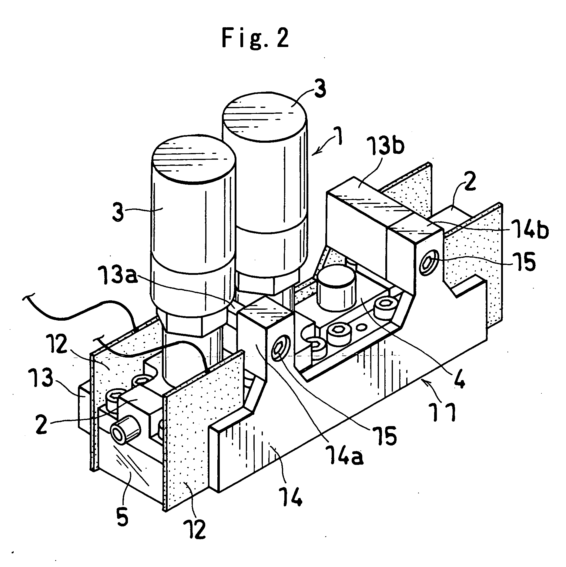
[0014]FIGS. 1 and 2 show a part of a fluid control apparatus with a heating apparatus in accordance with the invention. A fluid control apparatus 1 is formed such that lines formed by a plurality of fluid control devices 2, 3 and 4 arranged in an upper stage and a plurality of block-like joint members 5 arranged in a lower stage are arranged in parallel in a base member (not shown).

[0015] A heating apparatus 11 has sheet heaters 12 arranged in both right and left sides of at least one line and heating the fluid control devices 2, 3 and 4 and the joint members 5, left and right heat insulating boards 13 and 14 made of an engineering plastic are brought into contact with left and right outer sides of the sheet heaters 12, and the left and right heat insulating boards 13 and 14 facing to each other are coupled by two bolts (at least one thread member)...


PUM


Abstract

A heating apparatus (11) has sheet heaters (12) arranged in both sides of at least one line and heating fluid control devices (2, 3, 4) and joint members (5), heat insulating boards (13, 14) made of an engineering plastic are respectively brought into contact with outer sides of the sheet heaters (12), and the heat insulating boards (13, 14) are coupled to each other by at least one thread member (15), whereby the sheet heater (12) is prevented from dropping out.

Description

TECHNICAL FIELD [0001] The present invention relates to a fluid control apparatus used in a semiconductor manufacturing apparatus or the like, and more particularly to a fluid control apparatus with a heating apparatus. BACKGROUND ART [0002] A fluid control apparatus used in a semiconductor manufacturing apparatus is structured such that various fluid control devices are arranged in plural lines, and flow paths of the fluid control devices in adjacent lines are connected at a predetermined position by a device connecting means. In recent years, however, this kind of fluid control apparatus has been made progressively integrated by connecting a mass flow controller, an opening and closing valve and the like without any tube. [0003] In this kind of fluid control apparatus, there is a case that a heating apparatus is required for the purpose of such as condensation prevention and reliquefaction prevention at a time of gasifying a fluid, which is a liquid at room temperature, so as to f...

Claims


Application Information

Patent Timeline
IPC IPC(8): F16K49/00F16K27/00F16K51/02
CPCF16K27/003F16K51/02F16K49/00Y10T137/6606Y10T137/87885
Inventor SHIKATA, IZURUTANAKA, SHIGEAKIYAMAJI, MICHIO
Owner FUJIKIN INC
Why Eureka
Try Eureka