Universal vehicle engine, gearbox and like stand

a technology for vehicles and gearboxes, applied in the field of universal stands, can solve the problems of not being completely secure on the stand, the lower handle is too small,

Inactive Publication Date: 2007-07-26
NIKOLIC LJUBOMIR
View PDF5 Cites 2 Cited by
  • Summary
  • Abstract
  • Description
  • Claims
  • Application Information

AI Technical Summary

Benefits of technology

[0008] It is a primary object of the present invention to provide an improved universal vehicle engine, gearbox and

Problems solved by technology

Also some large engine have upper holes mentioned in previous paragraph positioned so close to lower holes that upper handles close to lower handles

Method used


Image

  • Universal vehicle engine, gearbox and like stand
  • Universal vehicle engine, gearbox and like stand
  • Universal vehicle engine, gearbox and like stand

Examples


Embodiment Construction

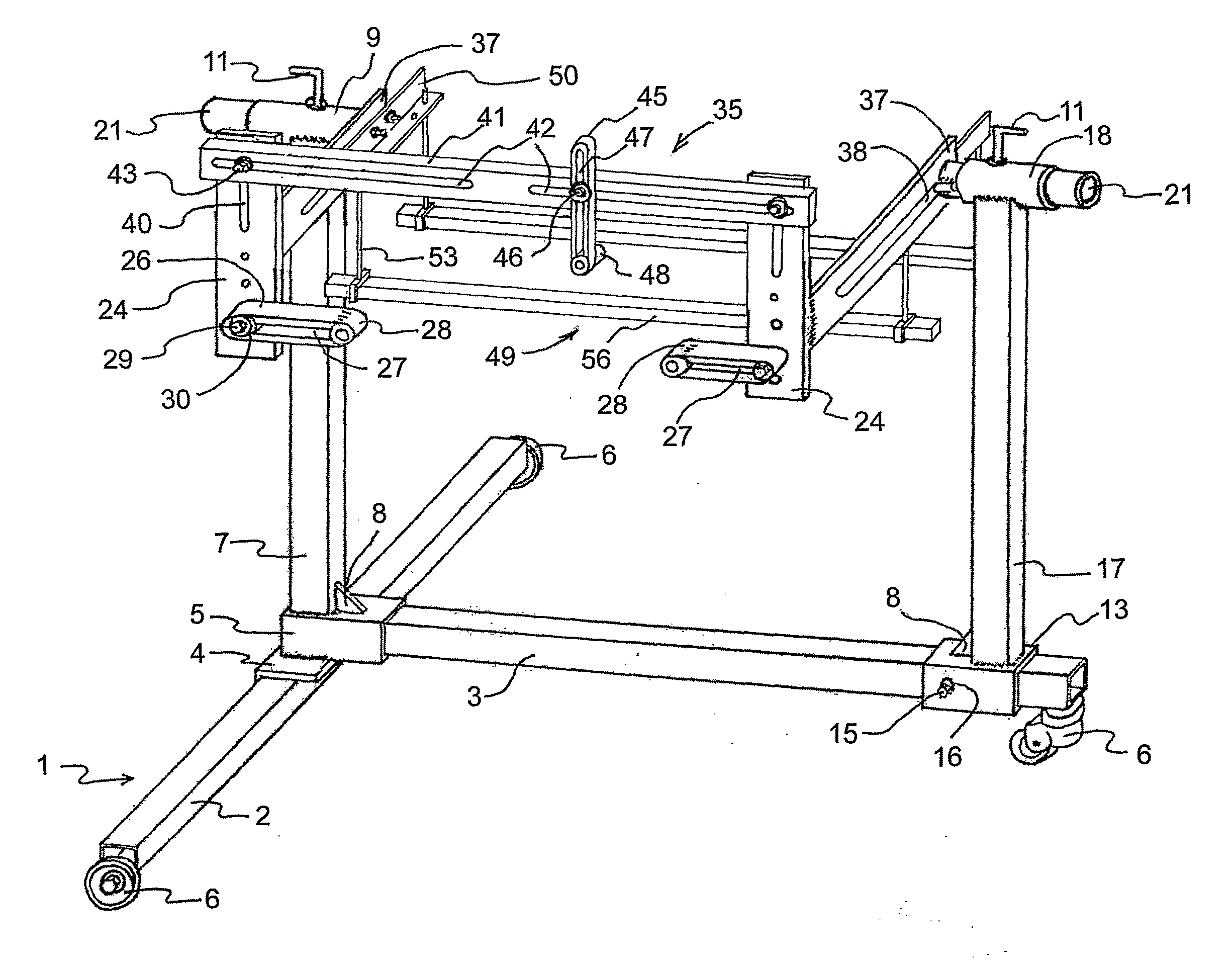
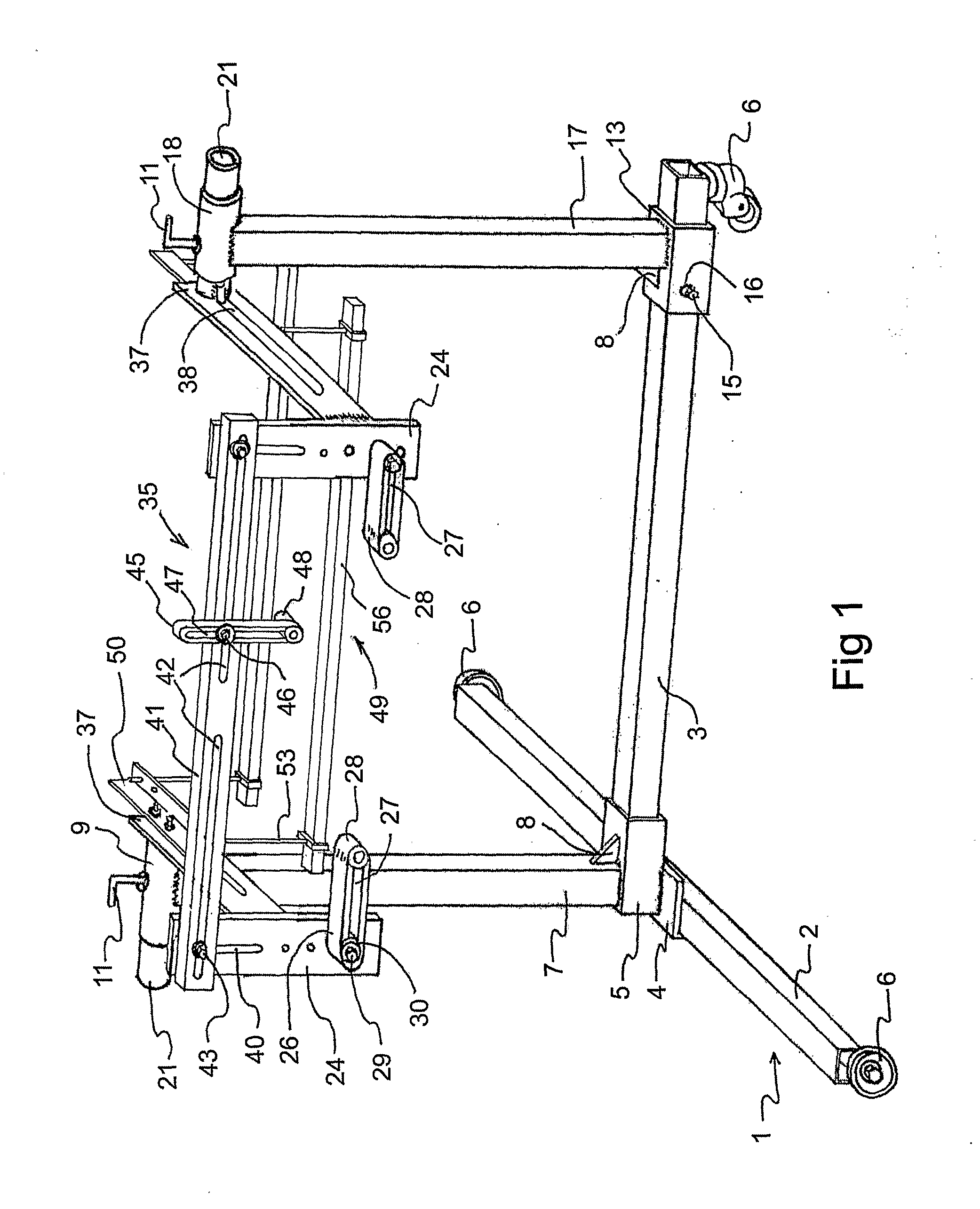
[0021] Reference will now be made in detail to the present preferred embodiment of invention, an example of which is illustrated in the accompanying drawings:

[0022] Referring to FIG. 1 the present invention includes standard T-shaped base (1) rather placed on the wheels (6) one of which is rather castor. The base includes two legs (2,3) connected rather by a bolt with L-shaped means (4) and connecting means (5) which are, in illustrated embodiment, welded. The invention further includes two vertical supports (7, 17). The vertical support (7) is firmly connected to the connecting means (5) and being stationary, and the vertical support (17) is firmly connected to the foot (13). The foot (13) is placed rather around the leg (3) capable of moving along the length of the leg (3) and has locking means (15,16) provided to lock foot in desired position. Two horizontal supports (9, 18) are firmly connected to the respective tops of the vertical supports (7, 17) to receive respective rotata...


PUM


Abstract

A improved stand enabling a rear engine plate and fly wheel to be removed from and return to the engine while the engine is on the stand and securely hold the engine and gearboxes on the stand regardless of type, size and weight thereof. Includes a base structure (1), a stationary vertical support (7), a movable vertical support (17), two horizontal supports (9, 18), two rotatable adjustable arms (21) to rotate the engine, a pair of adjustable connecting means (37), a pair of carrying plates (24), a bar means (41) to connect the carrying plates, three handles (26, 45) to hold engine from three directions, two L-shaped bar members to be engaged with two pairs of respective bolts fixed on the respective arms (21), two pair long bolts (53), two pairs of frames (55) and a pair of supports (56) to support the engine while the engine is released of the handles.

Description

TECHNICAL FIELD [0001] This invention relates to universal stand which provides secure holding various types of vehicle engines and gearboxes and allowing clear access to every side thereof during repair and renovation. BECKGROUND ART [0002] International patent application PCT / IB02 / 03439 discloses the universal stand capable of holding various types of engines and gearboxes allowing clear access to every side thereof during repair and renovation. [0003] Nevertheless, in said invention it is found that a rear engine plate, that some engines have and which positioned between engine block and fly wheel, cannot be removed from engine while engine is bolted on the stand. [0004] Beside that, some engine have upper holes, which holes are used for bolting engine on the stand, positioned close to each other. In that case upper handles coupled on respective carrying plat have to be longer than lower handles also coupled on respective carrying plat and because of that may happened that upper ...

Claims


Application Information

Patent Timeline
IPC IPC(8): B23Q1/25B25H1/00
CPCB25H1/0007
Inventor NIKOLIC, LJUBOMIR
Owner NIKOLIC LJUBOMIR
Why Eureka
Try Eureka