Pixel patterns

a technology of pixel pattern and pattern, applied in the field of electronic imaging devices, can solve the problems of insufficient high resolution, inability to achieve uncomplicated solutions, and pixel regularity holds the danger of aliasing, so as to minimise the risk and minimise the risk

Inactive Publication Date: 2007-07-26
TRANSPACIFIC INTELLIGENCE
View PDF8 Cites 202 Cited by
  • Summary
  • Abstract
  • Description
  • Claims
  • Application Information

AI Technical Summary

Benefits of technology

[0026] The effect of the invention may be explained by a schematic example, which is not intended to limit the invention in any way. As already indicated above it is well known that a suitable mix of for example red, green and blue colours can produce almost all colours visible to the human eye, where e.g. yellow is a mix of green and red. A yellow pattern in an image may therefore interfere with the green and red pixel patterns in known pixel arrays. However, according to the present invention a yellow pattern may at the most interfere with one of the green or the red pixel patterns, since the invention provides for a green pixel pattern and a red pixel pattern with different spatial frequencies, which frequencies are non-harmonics. Hence, a possible beat pattern will appear much weaker compared to a beat pattern formed by both the red and the green pixel patterns in combination. This weakening of a possible beat pattern applies for all image patterns having a colour that is composed by a mix of at least two of the red, green and blue colours, provided that the pixel patterns for the red, green and blue colours have different and non-harmonic spatial frequencies.
[0027] Nevertheless, a possible occurrence of a beat pattern will not be weakened if the interfering image pattern is composed of a single red, green or blue colour. It is therefore preferred, in addition to arranging pixels of different colours at different spatial frequencies, that pixels of the same colour are irregularly arranged and / or arranged at several spatial frequencies. This will minimise the risk that an image pattern will interfere with the pixel pattern or at least minimise the risk that an image pattern will interfere with all the pixels in the pixel pattern.
[0028] Even though the red, green and blue colours have been discussed as an illustrative example above the same conditions are valid for other colour combinations that may be more fitting in certain applications, e.g. the complementary colours cyan, magenta and yellow.
[0029] In the light of the above it is preferred that not only pixels of different colours but also pixels having the same colour are arranged according to as many short spatial frequencies as possible, where none or at least as few as possible of the frequencies are harmonics of each other. This makes it less likely that an image pattern will interfere with most or all of the short spatial wavelengths found in the pixel pattern to produce a beat pattern.
[0030] Accordingly, the present invention provides for an array of pixels comprising at least a first set of pixels representing a first colour and a second set of pixels representing a second colour and a third set of pixels representing a third colour. The array is characterised in that the pixels in said first set of pixels representing a first colour and / or the pixels in said second set of pixels representing a second colour are arranged in at least a first spatial frequency. Furthermore, the pixels in said third set of pixels representing a third colour are arranged in at least a second spatial frequency. Moreover, an array of pixels according to at least one embodiment of the present invention is characterised in that the pixels in one of said first set of pixels or said second set of pixels are arranged in at least a third spatial frequency.
[0031] None of said first, second and third spatial frequency—and in general as few as possible of all the spatial frequencies occurring in an array of pixels—are harmonics of each other, i.e. a frequency should not be an integer value of another frequency. For example, if said first spatial frequency is f cycles / m then said second and third spatial frequencies should not adopt any of the frequencies f / 2, f / 3, f / 4 . . . f / n, or 2f, 3f, 4f . . . nf, where n is an integer value.

Problems solved by technology

As electronic image-recording and electronic image-reproducing devices are susceptible to aliasing, primarily caused by the regularity in which the utilized pixels are arranged, but also caused by low pixel resolution, there is a need for an uncomplicated solution to this problem.
However, despite regular and therefore dense packing of the pixels the resolution in many applications of electronic imaging is still not high enough to avoid aliasing, and then the pixel regularity holds the danger of aliasing.

Method used


Image

  • Pixel patterns
  • Pixel patterns
  • Pixel patterns

Examples


first embodiment

A First Embodiment

Square Pattern

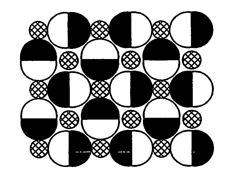
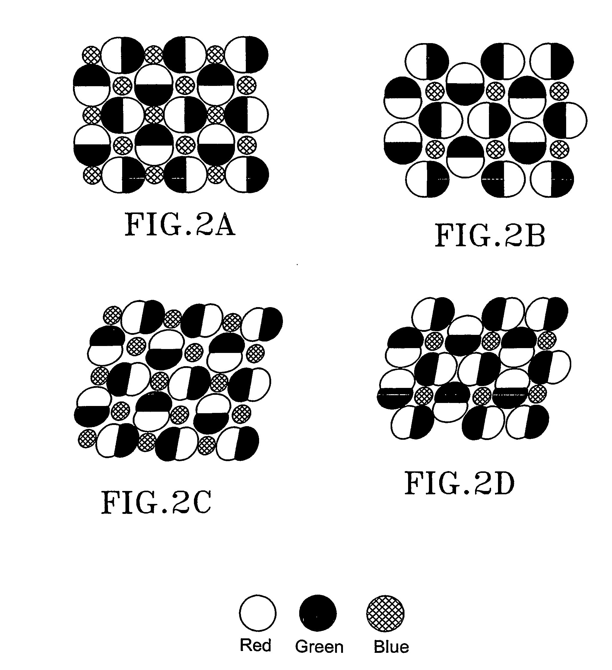
[0057] According to a first embodiment of this invention shown in FIG. 2A the risk of such aliasing is reduced. The pixel array illustrated in FIG. 2A is composed of double pixels and single pixels, which occur in about a 1 double:1 single pixel ratio in an array of pixels. It is preferred that the single pixels represent a blue colour, whereas the two pixels in the double pixel represent a red colour and a green colour respectively. Said pixels may in other embodiments represent other colours, depending on the specific application, the surrounding environment etc. An example of other possible colours is the complementary colours cyan, magenta and yellow.

[0058] The pixels in the first embodiment are arranged in a “square pattern”, where four double pixels occupy the sides of a square. A first double pixel is horizontally arranged at the bottom of the square, while three further double pixels are preferably arranged at the remaining sides of the squa...

second embodiment

A Second Embodiment

Shifted Square Pattern

[0065] According to a second embodiment of this invention shown in FIG. 2B the risk of aliasing is reduced in a similar way as in the previously discussed first embodiment of this invention as shown in FIG. 2A.

[0066] The pixel array illustrated in FIG. 2B is composed of double pixels and single pixels, which occur in about a 2 double:1 single pixel ratio in an array of pixels. In this embodiment, as In the first embodiment, it is preferred that the single pixels represent a blue colour, whereas the two pixels in the double pixel represent a red colour and a green colour respectively. Said pixels may in other embodiments represent other colours, depending on the specific application, the surrounding environment etc. An example of other possible colours is the complementary colours cyan, magenta and yellow.

[0067] The pixels in the second embodiment are arranged in a square pattern where four double pixels occupy the sides of a square, much i...

third embodiment

A Third Embodiment

Shifted Square Pattern

[0077] According to a third embodiment of this invention shown in FIG. 2E the risk of aliasing is reduced in a similar way as in the previously discussed second embodiment of this invention as shown in FIG. 2B.

[0078] In the third embodiment, as in the second embodiment, the pixel array illustrated in FIG. 2E is composed of double pixels and single pixels, which occur in about a 2 double:1 single pixel ratio in an array of pixels. In this embodiment, as in the second embodiment, it is preferred that the single pixels represent a blue colour, whereas the two pixels in the double pixel represent a red colour and a green colour respectively.

[0079] The pixels in the third embodiment are arranged in a “shifted square pattern” where four double pixels occupy the sides of a square in a similar way as in the previously discussed second embodiment. Consequently, a first double pixel is horizontally arranged at the bottom of the square, while three fu...


PUM

PropertyMeasurementUnit
crossing anglesaaaaaaaaaa
angleaaaaaaaaaa
turning anglesaaaaaaaaaa

Abstract

The invention discloses an array of pixels to be arranged in electronic color imaging devices, where the risk of aliasing is reduced by arranging the pixels in the array according to irregular patterns. The array is provided with a first, a second and a third set of pixels representing a first, a second and a third color respectively. The pixels in the first set of pixels and / or the pixels in the second set of pixels are arranged in at least a first spatial frequency, and the pixels in the third set of pixels are arranged in at least a second spatial frequency. In addition, one of said first or second set of pixels may be arranged in at least a third spatial frequency. None of said first, second and third spatial frequencies are harmonics of each other. The array may be implemented in one or several different matrixes of pixels.

Description

FIELD OF THE INVENTION [0001] The invention relates to electronic imaging devices susceptible to aliasing, where the aliasing is primarily caused by the regularity in which pixels are arranged in image recording or image reproducing arrays used by such devices. Especially, the invention relates to electronic recording and reproduction of colour images. BACKGROUND OF THE INVENTION INTRODUCTION [0002] In electronic cameras, scanners (including a digital scanner comprised by copying machines, fax machines etc) and in other electronic image-recording devices the image is normally projected or otherwise received on an array of light sensitive elements. Each element translates the received light into an electronic signal, which corresponds to the intensity of the received light. A whole image can therefore be recorded as an array of values received from an array of discrete light sensitive elements, where a specific value corresponds to the light received by a specific element in a specif...

Claims


Application Information

Patent Timeline
Patent Type & Authority Applications(United States)
IPC IPC(8): H04N9/04G02FG06T3/40G09G3/20G09G3/36
CPCG06T3/4015G09G3/2003G09G2320/0242G09G2300/0452G09G3/3607
Inventor KROGER, RONALD
Owner TRANSPACIFIC INTELLIGENCE
Why Eureka
Try Eureka