Flagstick with integrated reflectors for use with a laser range finder

a laser range finder and integrated reflector technology, applied in distance measurement, surveying and navigation, instruments, etc., can solve the problems of increasing the height of the pole, forming a discernible, and increasing the weight of the pol

Inactive Publication Date: 2007-07-26
GOLF SOLUTIONS 1
View PDF19 Cites 61 Cited by
  • Summary
  • Abstract
  • Description
  • Claims
  • Application Information

AI Technical Summary

Benefits of technology

[0004]An exemplary embodiment of the invention provides a system and a method for providing a plurality of reflectors mounted in a pole without increasing the diameter, height, or shape of the pole and insignificantly changing the weight of the pole. Each of the plurality of reflectors is mounted in the pole individually by drilling appropriately sized and shaped sockets in the pole. Failure of the mounting of the reflectors in the sockets does not result in a broken pole.

Problems solved by technology

Mounting a reflector device to the pole increases the weight of the pole, forms a discernible seam where the reflector device mounts to the pole, increases the height of the pole, and may form a pronounced bump or indentation in the pole if the diameter of the reflector device is different than the pole diameter.
Failure of the glue results in a broken pole.

Method used


Image

  • Flagstick with integrated reflectors for use with a laser range finder
  • Flagstick with integrated reflectors for use with a laser range finder
  • Flagstick with integrated reflectors for use with a laser range finder

Examples


Embodiment Construction

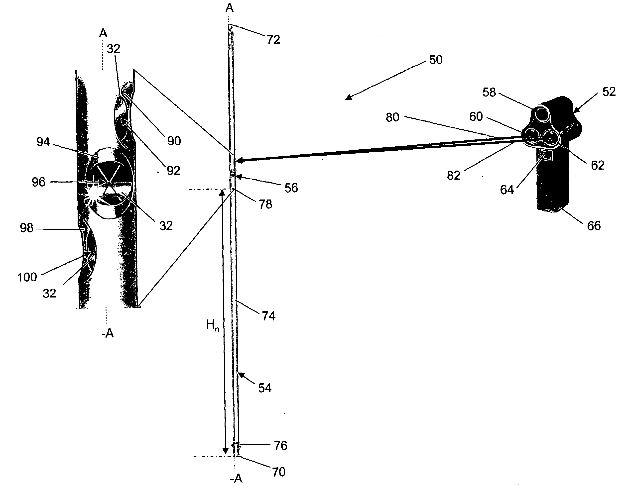
[0025]With reference to FIG. 1, a distance measuring system 50 is shown in accordance with an exemplary embodiment. Distance measuring system 50 includes, but is not limited to, a laser range finder 52 and a pole 54. The laser range finder 52 may include an aiming light source 58, a laser light source 60, a laser light receptor 62, a measurement button 64, a handle 66, and a processor (not shown). The aiming light source 58 transmits a light, for example a red light, toward a current aiming point so that the user can visually identify where the laser range finder 52 is currently aimed. The laser light source 60 transmits laser light toward the current aiming point when the measurement button 64 is depressed by the user. For example, laser light source 60 transmits light along a transmission path 80 toward the pole 54. In an exemplary embodiment, the laser light may be transmitted in a series of pulses. The laser light source 60 may be a Class 1 laser as known to those skilled in the...


PUM


Abstract

A system is provided for determining a distance to a target. In an exemplary embodiment, the system includes a pole and a distance measuring device. The pole includes a plurality of sockets formed in a surface of the pole above a selected lower reflecting point and a reflector mounted in each of the plurality of sockets. The lower reflecting point defines a minimum distance from a first end of the pole above which the reflectors are located for use with the distance measuring device. At least a portion of a signal received from the distance measuring device is reflected back to the distance measuring device by a receiving reflector. The distance measuring device includes a transmitter that transmits the signal at a first time, a receptor that receives the reflected signal from the receiving reflector at a second time, and a processor to determine the distance from the transmitter to the receiving reflector using the first time and the second time.

Description

FIELD OF THE INVENTION[0001]The present invention is related to systems for determining a distance to an object. More specifically, the present invention relates to a plurality of reflectors integrated with a flagstick, and the use of laser light to calculate a distance from a laser light source to the location of one of the plurality of reflectors.BACKGROUND OF THE INVENTION[0002]Laser light can be used to measure the distance from a laser light source to a target object. To measure distance, a laser transmits pulses of light toward an intended target. The light is reflected from the target and is received by a receptor. A calculation is made to determine the distance to the target based on the elapsed travel time between the transmission of the pulse of light and the reception of the reflected pulse of light. To improve performance, a reflector can be mounted to the target object to reflect a higher percentage of the transmitted light towards the receptor. For example, as disclose...

Claims


Application Information

Patent Timeline
Patent Type & Authority Applications(United States)
IPC IPC(8): G01C3/08
CPCG01S7/48G01C3/08
Inventor STEINER, DANIELO'LOUGHLIN, ROBTIMBERMAN, WAYNEPLITMAN, MICHAEL
Owner GOLF SOLUTIONS 1
Why Eureka
Try Eureka