Modular installation concept for a camera

a module installation and camera technology, applied in the field of surveillance camera installation, to achieve the effect of preventing undesired shifting from the installation position, reducing installation costs, and reducing installation costs

Inactive Publication Date: 2007-07-26
AIRBUS OPERATIONS GMBH
View PDF5 Cites 15 Cited by
  • Summary
  • Abstract
  • Description
  • Claims
  • Application Information

AI Technical Summary

Benefits of technology

[0011] One advantage of an installation kit according to an embodiment of the present invention is that the installation of a camera in an aircraft is not restricted to regions in which a sufficient installation depth is available for the camera module. On the contrary, surveillance cameras may be arranged at arbitrary locations in a passenger cabin. The invention may also eliminate the significant installation expenditure associated with the initially described known installation concept, in which a reading lamp housing is utilized. The special mounting and adapter components that may have been required for the installation of a reading light housing may also be eliminated. A camera module may now be latched in either a suitable installation cutout in an installation wall or in a correspondingly realized installation cutout in the external mounting housing by utilizing the latching mechanism arranged thereon, i.e., no additional fastening means may be required.
[0012] In order to prevent the camera module from falling out of the installation cutout in the external mounting housing or the installation wall after its installation into the respective installation cutout, the camera module comprises a plurality of latching elements for latching the camera module in either the installation cutout in the installation wall or, alternatively, in the installation cutout in the external mounting housing. The camera housing of the camera module may furthermore feature at least one abutment surface that is suitable for contacting the outside of the installation cutout in order to thusly secure the camera module from falling into the installation cutout. The camera module therefore is secured by the at least one abutment surface in the installation direction and by the plurality of latching elements opposite to the installation direction such that the camera module is prevented from undesirably shifting from the installation position. Alternatively to securing the installation position of the camera module with the described combination of abutment surface and latching element, the latching elements may, according to another embodiment, be pivoted into corresponding recesses in the installation cutout in order to ensure that the camera module is secured in position.
[0013] The latching elements are arranged on the camera module such that they may be pivoted between a latching position and an unlatching position in order to achieve a simple latching process with the aid of the latching elements. The latching elements consequently may be realized in the form of simple latches that can be pivoted back and forth between two positions, for example, with the aid of a screwdriver, wherein the two positions are preferably offset relative to one another by an angle of 90°.
[0014] In order to ensure an optimal seat of the camera module in its installation position, in which the camera module may be latched in an installation cutout in the installation wall, the installation kit may furthermore comprise an installation frame that serves for latching the camera module in the installation cutout in the installation wall during its installation. This installation frame is initially fitted into the installation cutout in the installation wall in order to compensate a possibly inaccurate contour of the installation cutout. The utilization of an installation frame that has the same inside contour as the installation cutout in the external mounting housing may make it possible to ensure that any dimensional inaccuracies in producing the installation cutout in the installation wall are compensated.

Problems solved by technology

However, if the external mounting housing has a substantial depth, this may result in the camera module being arranged substantially in front of the installation wall such that no installation depth is required behind the installation wall for accommodating the camera body.

Method used


Image

  • Modular installation concept for a camera
  • Modular installation concept for a camera
  • Modular installation concept for a camera

Examples


Embodiment Construction

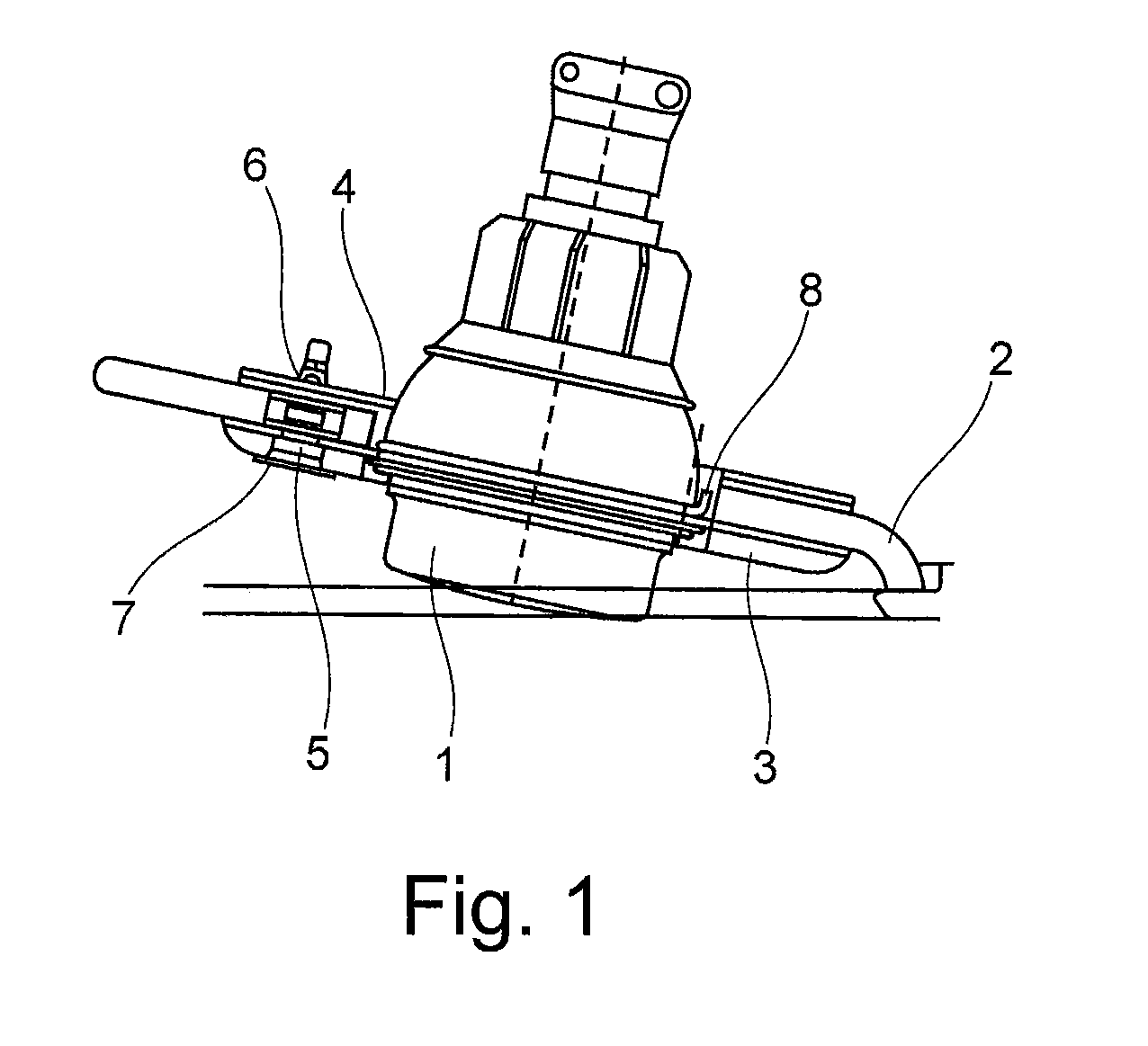
[0030] A known camera installation principle for a surveillance camera is initially described with reference to FIG. 1 in order to better elucidate the invention and to emphasize its advantages in comparison with a known camera installation principle. According to this figure, a camera that is not visibly illustrated in this figure is arranged in a housing 1 that normally serves as a housing for a reading lamp. This reading light housing 1 containing the camera is mounted in the ceiling 2 of an aircraft passenger cabin. An adapter ring 3 is screwed into and forms the border of an opening in the ceiling 2 in order to accommodate the reading light housing 1. This adapter ring 3 serves for solidly and positively accommodating the reading light housing 1 in the opening in the ceiling 2 in connection with another ring 8 extending around the reading light housing 1, as well as an inner fastening ring 4. In order to fix the reading light housing with the camera accommodated therein in the ...


PUM


Abstract

A modular installation system for the installation of camera provides an installation kit capable of being used either flush mounted or protruding on the wall of an aircraft cabin. An external mounting housing or a mounting frame may be used. A camera module includes a camera and mounting hardware including a latching mechanism. The camera module may be arranged substantially in front of the installation wall or substantially flush with the installation wall using the same latching mechanism of the camera module. An external housing may be used for housing the camera module such that the external housing mounts on a surface of a wall or partially inserted into a wall, and the external housing provides latching hardware for mating with the latching mechanism of the camera module. A mounting frame may be inserted in a wall cutout to provide latching hardware for mating with the latching mechanism of the camera module for substantially flush mounting. An external frame may be removably fitted onto the camera module.

Description

REFERENCE TO RELATED APPLICATIONS [0001] This application claims the benefit of the filing date of German Patent Application No. 10 2005 018 316.6 filed Apr. 20, 2005 and of U.S. Provisional Patent Application No. 60 / 673,058 filed Apr. 20, 2005, the disclosure of which applications is hereby incorporated herein by reference.FIELD OF THE INVENTION [0002] The present invention generally relates to the installation of surveillance cameras in an aircraft. The present invention specifically relates to a modular installation concept for installation of cameras, wherein different camera installation positions can be realized due to the utilization of a new installation kit. The invention furthermore relates to a camera module for installation on an installation wall of an aircraft. In addition, the invention pertains to the utilization of an external mounting housing for installing a camera module in an aircraft, as well as to an aircraft with at least one such camera module. TECHNOLOGICAL...

Claims


Application Information

Patent Timeline
Patent Type & Authority Applications(United States)
IPC IPC(8): G03B17/00
CPCG08B13/19619G03B17/02
Inventor DROEGE, FRANKWUSSOW, BURGHARD
Owner AIRBUS OPERATIONS GMBH
Why Eureka
Try Eureka