
Mounting button used in display module

a display module and button technology, applied in the field of mounting buttons, can solve the problems of large assembly operation, inconvenience in assembly, and large cost of the mechanism, and achieve the effect of improving production or repair efficiency, quick assembly or disassembly

Inactive Publication Date: 2007-07-26
CHUNGHWA PICTURE TUBES LTD
View PDF9 Cites 22 Cited by
  • Summary
  • Abstract
  • Description
  • Claims
  • Application Information

AI Technical Summary

Benefits of technology

[0010]Accordingly, the object of the present invention is to provide a mounting button, which is suitable for locking two plates in a display module and provides quicker assembly or disassembly for improving the efficiency of production or repair.
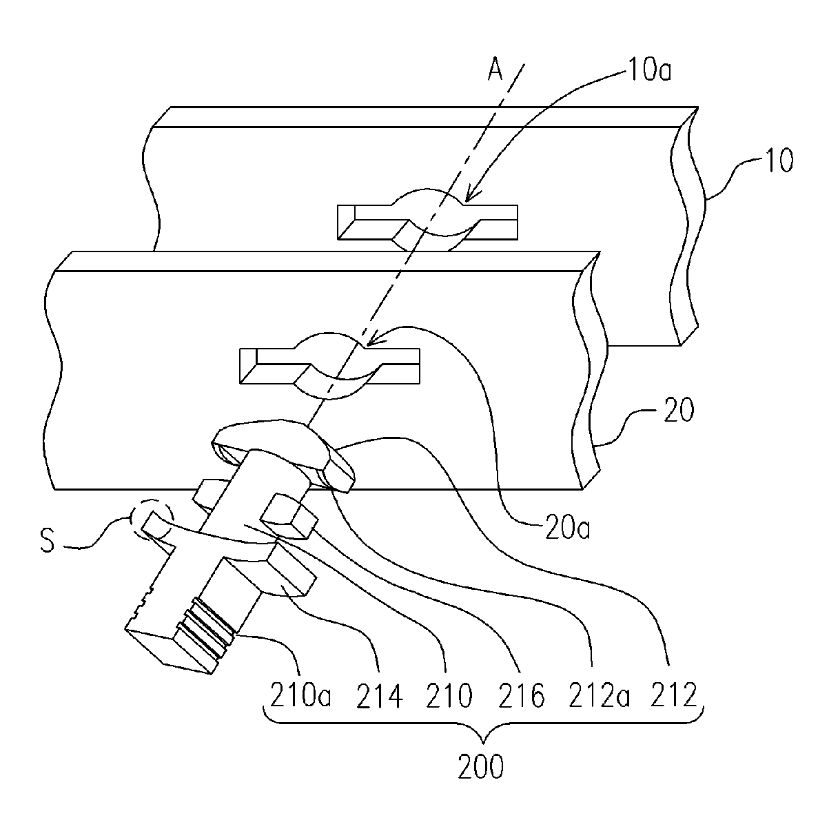
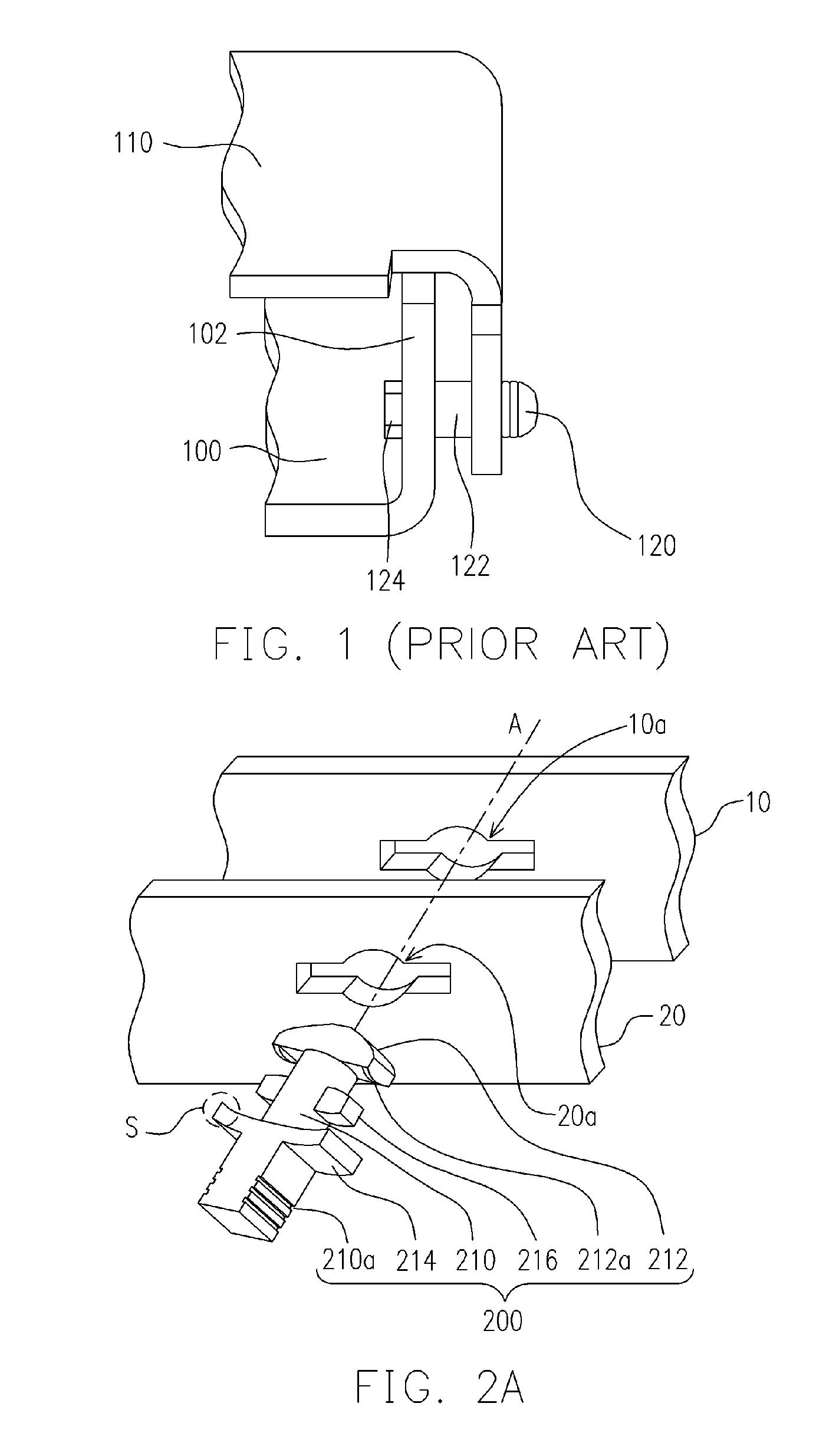
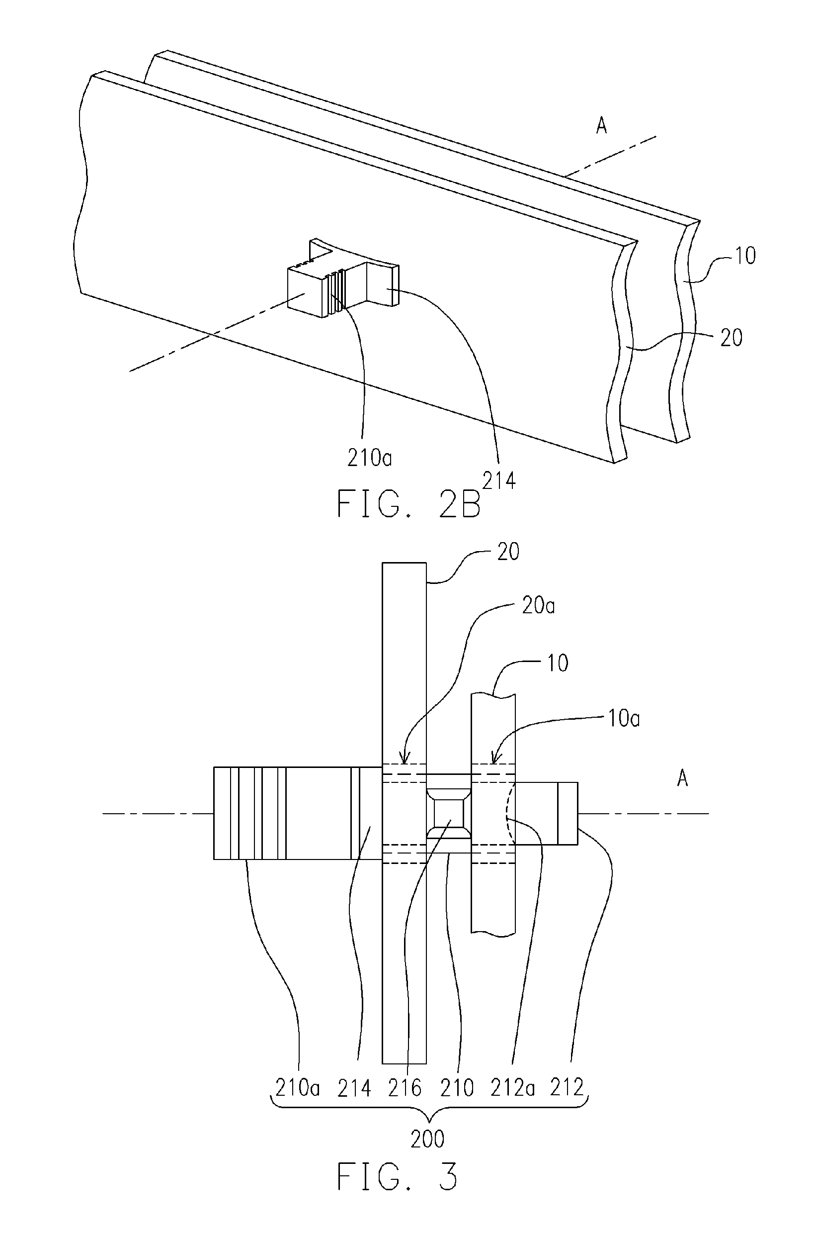
[0028]With the mounting button used in the display module of the present invention, the relative position of a first plate and a second plate in a display module can be fixed. The mounting button has a first sticking part and a second sticking part for supporting the two plates, and a spacing part for keeping a distance between the two plates. Therefore, compared with the conventional locking manner using screws, the mounting button of the present invention permits easy and rapid assembly or disassembly, thus reducing the operating time of the operator and the manufacturing cost, and improving the efficiency of production or repair.

Problems solved by technology

Currently, during the manufacture of the Plasma Display, the cost of the mechanism comprises a large proportion.
However, because the screws may be of different shapes and sizes, it takes too much time to select the screw driver or other tools, thus causing inconvenience in assembly.
Moreover, when using the screw driver or other assistant tools, the assembly operation may be limited by the design of the structure of the product and the operating space, and may not be able to be carried out successfully.
On the other hand, when the Plasma Display needs to be repaired or disassembled due to various reasons, the above problem also exists, thus consuming much time and labor in repair or disassembly.

Method used


Image

  • Mounting button used in display module
  • Mounting button used in display module
  • Mounting button used in display module

Examples


Embodiment Construction

[0035]The mounting button of the present invention is suitable for fixing the relative position of the two plates in the display module. The assembling of the back plate and the heat sink in the Plasma Display are taken as an example in the following to illustrate the manner of assembly using the mounting button of the present invention. Of course, the application scope of the mounting button of the present invention is not limited herein. With reference to the following embodiments, it will be apparent to those skilled in the art that the present invention can be applied in assembly involving plates of other display apparatuses as required.

[0036]FIGS. 2A˜2C are sequentially schematic views of assembling the back plate and the heat sink in the plasma display module of the preferred embodiment of the present invention. Referring to FIG. 2A, a heat sink 20 is disposed on the outer side of the edging 10 of the back plate of the plasma display module, wherein a first opening 10a is prov...


PUM


Abstract

A mounting button suitable for fixing the relative position of a first plate and a second plate in a display module is provided. The first plate has a first opening and the second plate has a second opening. The mounting button comprises a shaft, a first sticking part, a second sticking part, and a spacing part, wherein the first sticking part, the second sticking part, and the spacing part protrude from the shaft, and the spacing part is located between the first sticking part and the second sticking part. The mounting button used in the display module permits quicker assembly and disassembly for improving the efficiency of production and repair.

Description

CROSS-REFERENCE TO RELATED APPLICATION[0001]This application claims the priority benefit of Taiwan application serial no. 95102573, filed on Jan. 24, 2006. All disclosure of the Taiwan application is incorporated herein by reference.BACKGROUND OF THE INVENTION[0002]1. Field of Invention[0003]The present invention relates to a mounting button. More particularly, the present invention relates to a mounting button used in a display module.[0004]2. Description of Related Art[0005]The Flat Panel Display is a kind of communication interface between humans and information. Currently, Flat Panel Displays mainly include Plasma Displays, Organic Electro-Luminescent Displays (OELD), Liquid Crystal Displays (LCD), etc. Among them, the Plasma Display has large application potential due to its advantages of large size, self-luminescence, no visual angle dependence, lightness and thinness, true color, and so on, and will hopefully become the mainstream of the next-generation of Flat Panel Displays...

Claims


Application Information

Patent Timeline
IPC IPC(8): F16B19/00
CPCF16B5/065F16B21/02F16B19/02F16B5/0657
Inventor HSU, YAO-TUNG
Owner CHUNGHWA PICTURE TUBES LTD
Learn More