Expander
- Summary
- Abstract
- Description
- Claims
- Application Information
AI Technical Summary
Benefits of technology
Problems solved by technology
Method used
Image

Examples
first embodiment
[0087] Embodiments of the present invention will be explained with reference to the drawings.
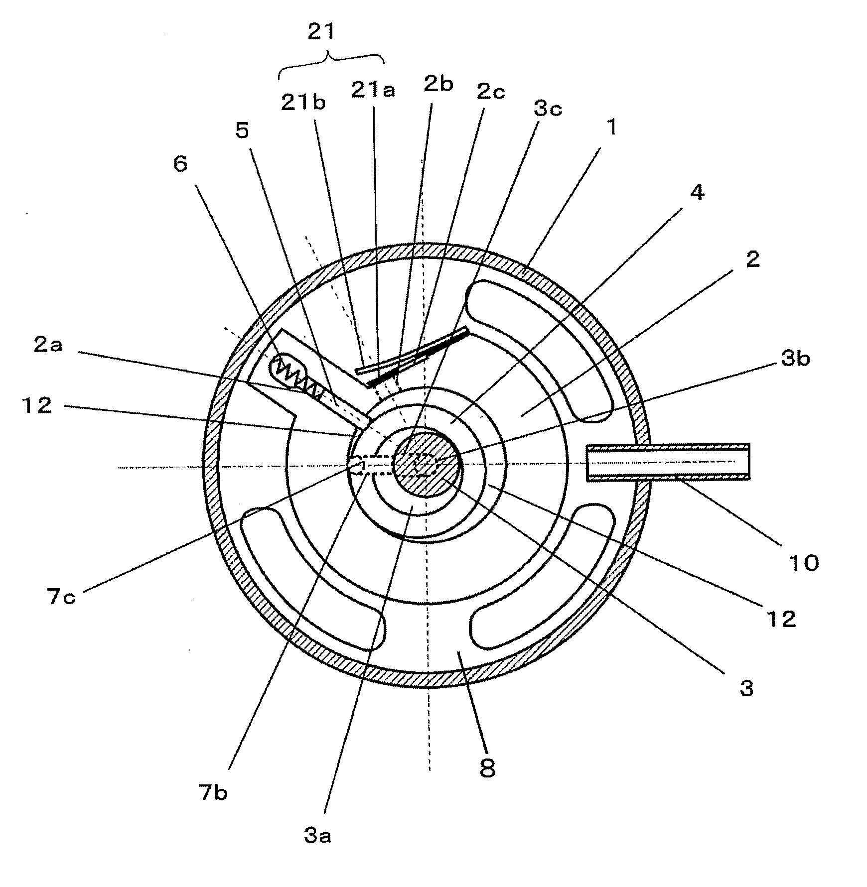
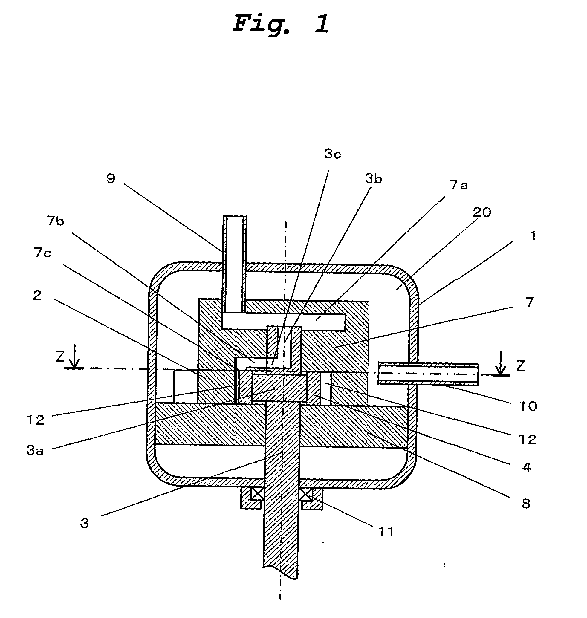
[0088] An expander in a first embodiment of the present invention has substantially the same structure as that of the conventional expander explained with reference to FIGS. 16 to 20 except that the discharge hole is provided with a differential pressure regulating valve. The same functional parts are designated with the same symbols, and explanation of the same structure and operation as those of the conventional example will be omitted. FIG. 1 is a vertical sectional view of the expander of the first embodiment. FIG. 2 is a transverse sectional view of the expander of the first embodiment. FIG. 1 corresponds to FIG. 16 showing the conventional expander, and FIG. 2 is the sectional view taken along the line Z-Z in FIG. 1.
[0089] The expander of this embodiment comprises a container 1, a cylinder 2 having a cylindrical inner wall, a shaft 3 having an eccentric portion 3a, a roller 4 which i...
second embodiment
[0108] An expander of a second embodiment of this invention is the same as that of the first embodiment except that positions of the discharge hole and the differential pressure regulating valve are changed. The same functional parts are designated with the same symbols, and explanation of the same structure and effect will be omitted.
[0109]FIG. 4 is a transverse sectional view of the expander of the second embodiment. FIG. 5 is a vertical sectional view of the expander of the second embodiment taken along the line Y-Y in FIG. 4.
[0110] In the expander of this embodiment, a lower bearing member 8 as a closing member for closing the lower end surface of the cylinder 2 is provided with a discharge hole 8a through which working fluid is discharged from the working chamber 12 into the discharge space 20, and the discharge hole 8a is provided with a differential pressure regulating valve 22. The differential pressure regulating valve 22 comprises a reed valve 22a and a valve stopper 22b...
third embodiment
[0118] An expander of a third embodiment of this invention is the same as that of the second embodiment except that shapes of the discharge hole and the differential pressure regulating valve are changed. The same functional parts are designated with the same symbols, and explanation of the same structure and effect will be omitted.
[0119]FIG. 6 is a vertical sectional view of the expander of the third embodiment of the invention.
[0120] According to the expander of the third embodiment, the lower bearing member 8 is provided with a discharge hole 8b whose portion closer to the working chamber 12 is formed into a circular conical surface. The expander is provided with a differential pressure regulating valve 23 for opening and closing the discharge hole 8b. The differential pressure regulating valve 23 comprises a valve portion 23a having such a circular conical surface that is fitted into the discharge hole 8b, a valve spring 23b for biasing the valve portion 23a against the discha...
PUM
 Abstract
Description
Claims
Application Information
 - R&D Engineer
- R&D Manager
- IP Professional
- Industry Leading Data Capabilities
- Powerful AI technology
- Patent DNA Extraction
Browse by: Latest US Patents, China's latest patents, Technical Efficacy Thesaurus, Application Domain, Technology Topic.
© 2024 PatSnap. All rights reserved.Legal|Privacy policy|Modern Slavery Act Transparency Statement|Sitemap