
Flexible hose for high pressures and temperatures including a charge-air hose and a cooling-water hose

a hose and high pressure technology, applied in the direction of engine cooling apparatus, combustion air/fuel air treatment, fuel intake, etc., can solve the problems of complicated curved geometries of hoses, difficult to produce hoses with expanded ends for fitting attachment, and difficult to produce hoses with complicated curved geometries. to achieve the effect of minimizing expansion

Inactive Publication Date: 2015-04-07
CONTITECH MGW GMBH
View PDF37 Cites 0 Cited by
  • Summary
  • Abstract
  • Description
  • Claims
  • Application Information

AI Technical Summary

Benefits of technology

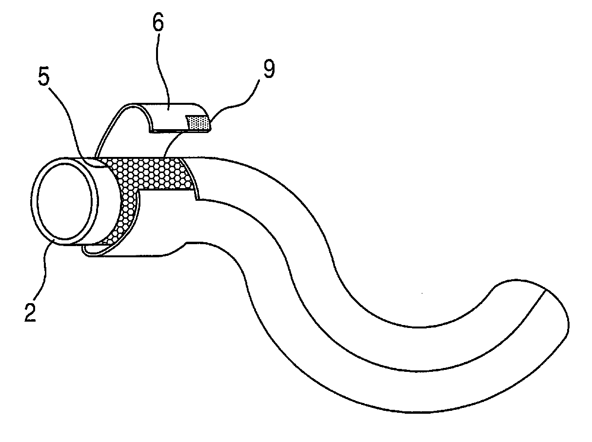
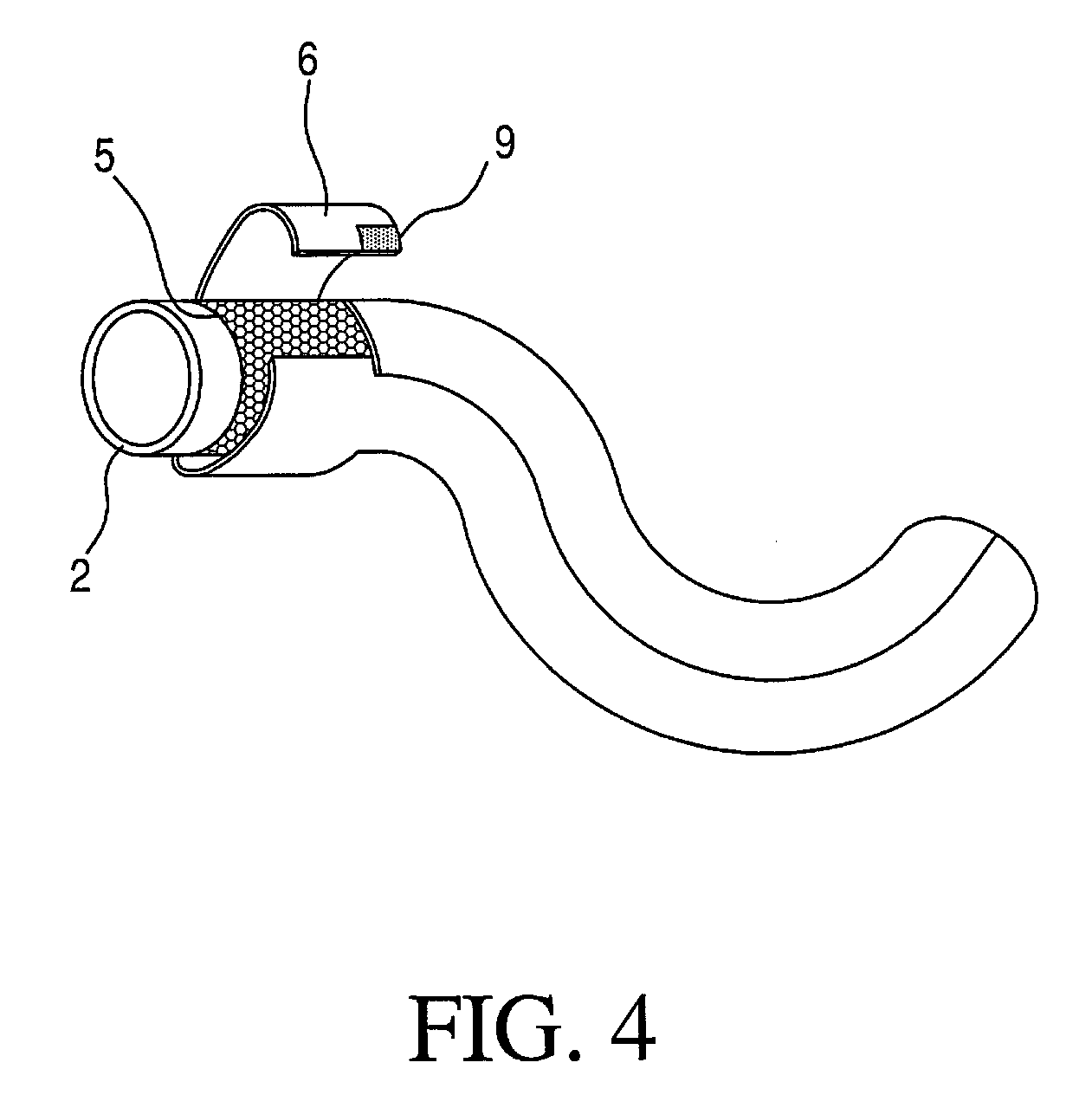
The invention provides a hose design with a tubular knit or braid reinforcement layer and a wound layer made of a textile layer that results in limited radial expansion of the hose and good axial flexibility under pressure loads. This design significantly increases the service life by avoiding defects and microcracks due to excessive stretching and allows for the manufacture of complex hose geometries. The wound textile reinforcement insert can also have been configured as an open braid which facilitates direct contact between rubberized wound layer and elastomeric inner layer. A second flat knit layer may be used to minimize expansion and distribute the pressure over three layers. One-sided rubberizing is more advantageous for total wall thickness and there is less change of wall thickness at the overlap location.

Problems solved by technology

Although the higher pressure resistance was satisfactory, it was very difficult to produce complicated curved-hose geometries because the increased stiffness of this type of hose limits small radii of the hose curves and larger expansion at the ends of the hose.
These wound hoses are resistant to high pressure but create difficulties in further processing, since, as the number of wound layers increases, the increase in stiffness makes it difficult to produce hoses with expanded ends for the attachment of fittings, and hoses with complicated curved geometries.
Although this is a flexible hose, it has low pressure resistance.
By virtue of the plurality of wound layers, this wound hose is excessively stiff and difficult to mold to curved geometries.

Method used


Image

  • Flexible hose for high pressures and temperatures including a charge-air hose and a cooling-water hose
  • Flexible hose for high pressures and temperatures including a charge-air hose and a cooling-water hose
  • Flexible hose for high pressures and temperatures including a charge-air hose and a cooling-water hose

Examples


Embodiment Construction

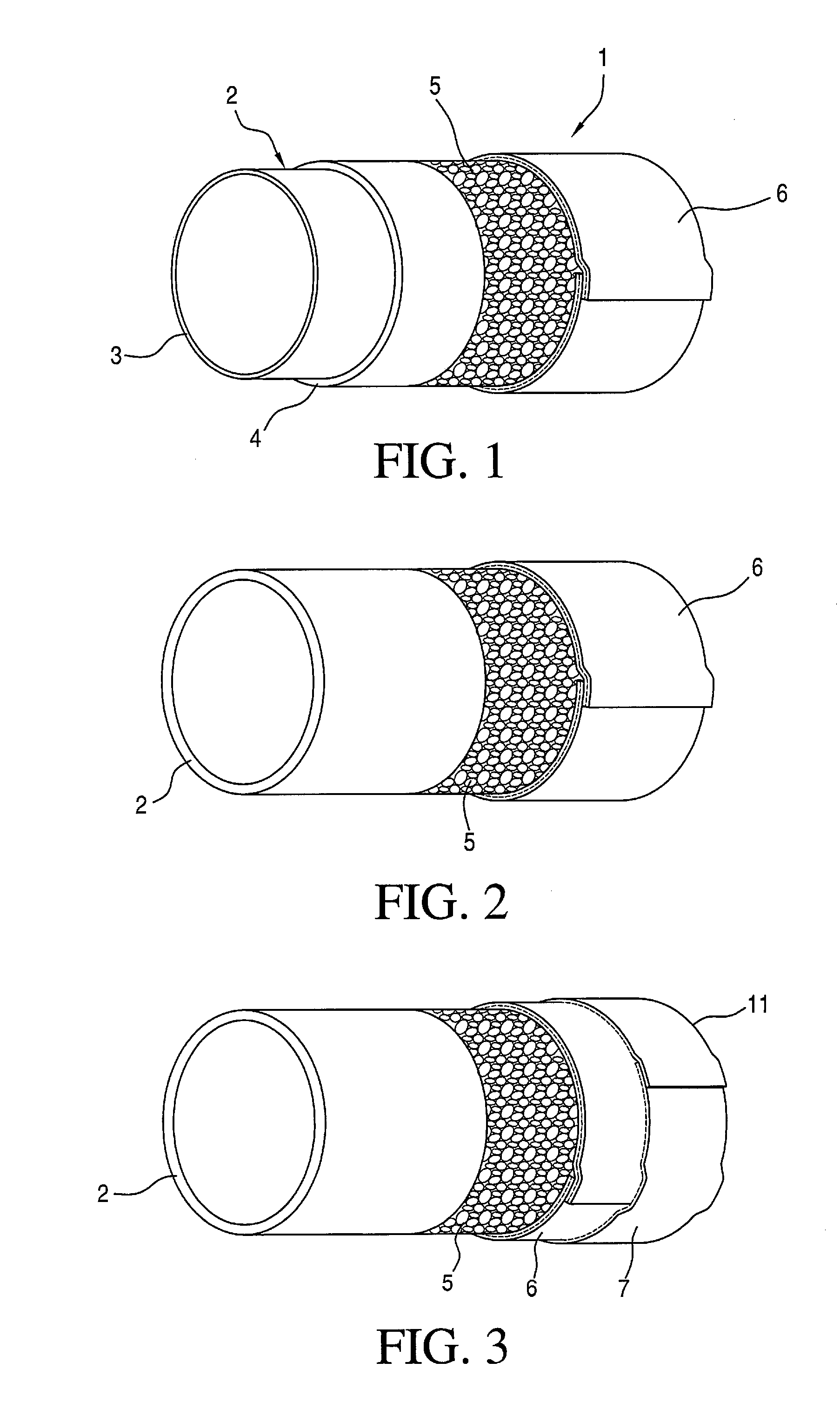
[0038]The charge-air hose 1 shown in FIG. 1 has a two-layer inner layer 2 extruded from elastomeric material and composed of an FPM (fluororubber) barrier layer 3 and a VMQ (silicone rubber) intermediate layer 4. On this inner layer 2, there is a tubular circular knit 5 applied, the yarn of which is made of m-aramid. A wound layer 6 made of bilaterally rubberized flat knit made of m-aramid is twice wound around the circular knit in an overlapping manner. The flat knit 6 is usually prerubberized in a calendering process.

[0039]Once this unvulcanized hose has been structured (manufactured), it is vulcanized to completion in an autoclave on a mandrel designed appropriately for the desired curvature geometry.

[0040]The hose structure in FIG. 2 differs from the hose structure of FIG. 1 in that the extruded elastomeric inner layer 2 has only a single layer. The elastomeric material of the inner layer 2 is a rubber material: AEM (ethylene-acrylate rubber). The material of the circular knit 5...


PUM

PropertyMeasurementUnit
pressuresaaaaaaaaaa
flexibleaaaaaaaaaa
curvatureaaaaaaaaaa

Abstract

A flexible hose (1) has at least two textile reinforcement inlays or inserts (5, 6, 7) and an inner layer (2) made of elastomeric material. The flexible hose can assume various curvature geometries and, on the other hand, is still pressure-resistant because a textile reinforcement inlay (5) made of a peripherally closed, tubular knitted or woven fabric is applied to the elastomeric inner layer (2). A textile layer (6), which is rubber-coated on both sides, is wound as a further textile reinforcement inlay onto the tubular knitted or woven fabric (5).

Description

CROSS REFERENCE TO RELATED APPLICATIONS[0001]This application is a continuation application of international patent application PCT / EP 2009 / 050297, filed Jan. 13, 2009, designating the United States and claiming priority from German applications 10 2008 009 598.2 and 10 2008 055 480.4, filed Feb. 15, 2008 and Dec. 5, 2008, respectively, and the entire content of all the applications is incorporated herein by reference.FIELD OF THE INVENTION[0002]The invention relates to a flexible hose for high pressures and temperatures having at least a textile reinforcement insert and an inner layer of elastomeric material.BACKGROUND OF THE INVENTION[0003]Charge-air hoses serve to connect a turbocharger to a charge-air cooler (hot end) and to connect a charge-air cooler to the engine (cold end). Both ends have to withstand pressures up to 3 bar overpressure and also have to compensate for the relative movement between engine and charge-air cooler.[0004]There are known charge-air hoses for charge-...

Claims


Application Information

Patent Timeline
Patent Type & Authority Patents(United States)
IPC IPC(8): F16L11/00F01P11/04F02M35/10F16L11/04F16L11/08
CPCF16L11/042F02M35/10321F02M35/10334F16L11/086F01P11/04F02M35/10157
Inventor LUDWIG, LIGIAWILL, GERHARDDILL, ROBERT
Owner CONTITECH MGW GMBH
Learn More