Craniotomy closures and plugs

a cranial closure and plug technology, applied in the field of surgical strips, can solve the problems of cosmetically objectionable depressed areas, low safety, and high cost, and achieve the effect of maintaining the skull contour

a cranial closure and plug technology, applied in the field of surgical strips, can solve the problems of cosmetically objectionable depressed areas, low safety, and high cost, and achieve the effect of maintaining the skull contour

US20070173844A1Active Publication Date: 2007-07-26NEW AMSTERDAM LLC

Image

  • Craniotomy closures and plugs
  • Craniotomy closures and plugs
  • Craniotomy closures and plugs

Examples


Embodiment Construction

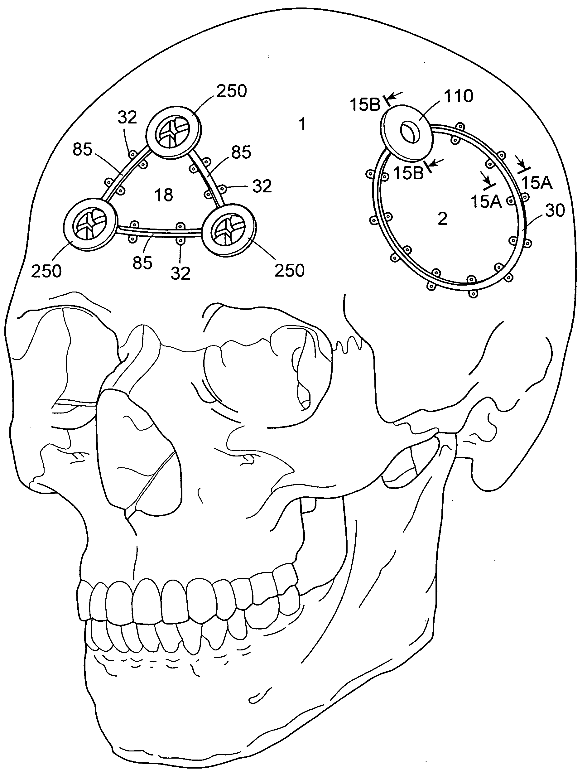
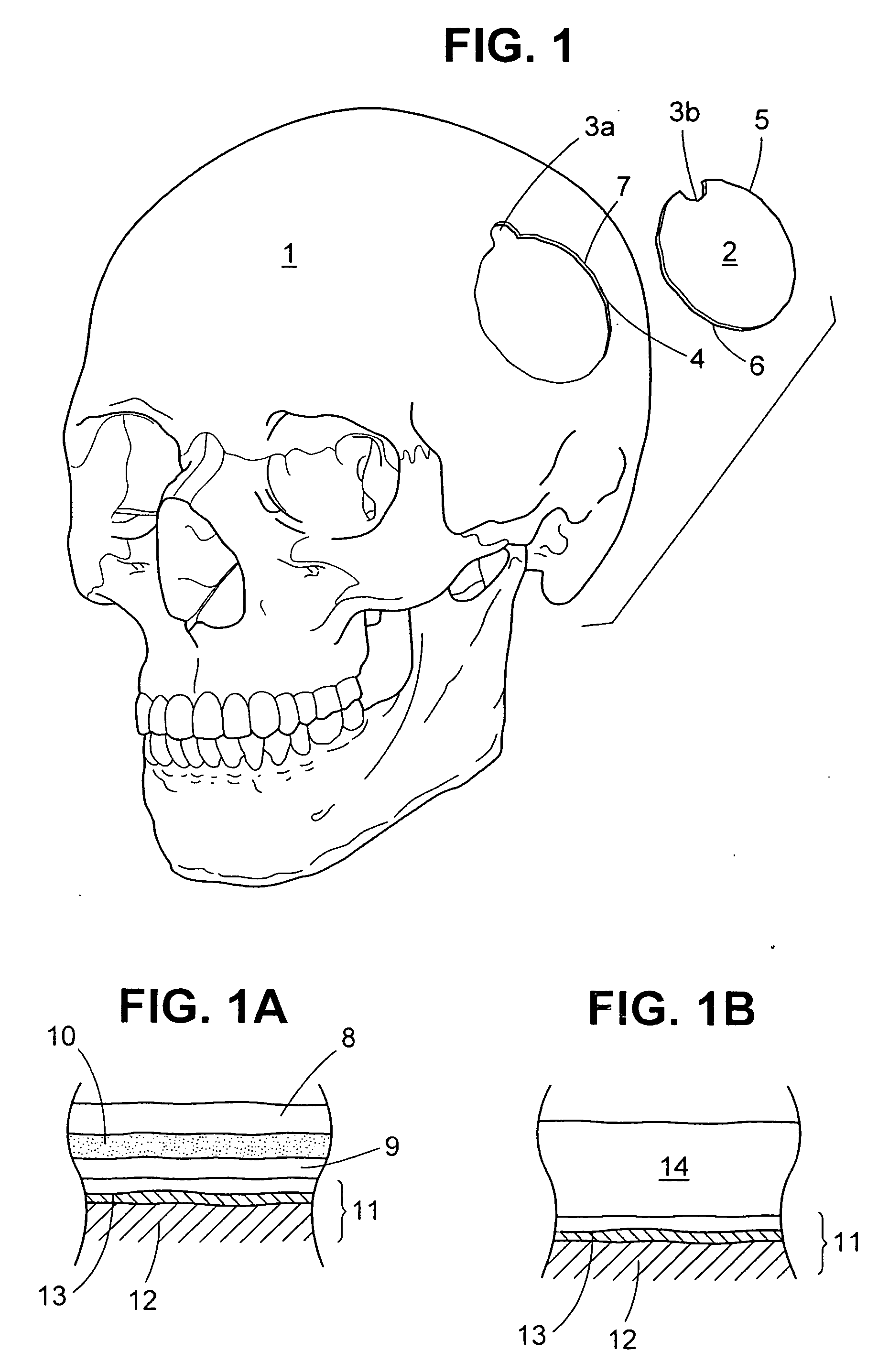
[0060] For reference, a human skull 1 with a craniotomy skull flap 2 is shown in FIG. 1. The skull flap 2 is defined by a burr hole 3 and the connecting osteotomy cut 4, wherein the skull portion of the burr hole is designated in FIG. 1 as 3a and the skull flap as 3b. The skull flap 2 has a perimeter contour 5 but it need not be of the particular shape shown and may have any number of burr holes 3. (See FIG. 15 for a 3 burr hole configuration.) On the opposing sides of the osteotomy cut 4 is the respective bone edge surface 6 of the skull flap 2 and the surrounding bone 7 of the skull 1, respectively. The bone edge surface 6 has a perimeter contour 5 generally matching the contour of the surrounding bone 7 of skull 1.

[0061] The skull 1 and skull flap 2 are either made from bone that has a three layer composition, as shown in FIG. 1A, or a single layer as shown in FIG. 1B. Referring to FIG. 1A, the outermost layer is the outer cortical bone 8 and the innermost layer is the inner cor...


PUM


Abstract

Strip fasteners and cranial plugs for use in reattaching a skull flap removed during brain surgery and methods of using the same. The strip fasteners are flexible and can be shaped to follow the perimeter contour of the skull flap. The cranial plugs can be used to reattach the skull flap or they can be installed after the skull flap is reattached using the strip fasteners. In some embodiments, the cranial plug(s) and strip fasteners can be installed at the same time. The strip fasteners and cranial plugs are designed to encourage bone growth and healing of the skull flap and they can be used to deliver medication and bone growth enhancement compositions to the surgical site.

Description

FIELD OF THE INVENTION [0001] The invention relates to surgical strip fasteners, particularly for use in reattaching a skull flap removed during brain surgery, and methods of reattaching the skull flap using the strip fasteners. The invention also has to do with cranial plugs used to fill small openings in the cranium or the burr holes made to facilitate cutting out a skull flap. In a further aspect, the invention relates to surgical strip fasteners and cranial plugs and methods which enhance bone growth and the consequent healing of the skull flap and the skull. BACKGROUND OF THE INVENTION [0002] Surgical access to the brain for neurosurgical procedures is created by removing a portion of the patient's skull, a procedure termed a craniotomy. The craniotomy is determined by the location of the pathology within the brain, the safest / easiest access route and the degree of exposure required for the procedure. Once the location is determined, the first step is to create an initial perfo...

Claims


Application Information

Patent Timeline
26 Jul 2007
Publication
US20070173844A1
IPC
A61B17/58
CPC
Y10T403/7176; A61B17/688; A61B17/68; A61B17/58
Inventors
RALPH, JAMES D.; TROXELL, THOMAS N.