Nursing bed with improved lifting mechanism

a technology for nursing beds and lifting mechanisms, applied in nursing beds, rigid tables, medical science, etc., can solve the problem that the lifting mechanism cannot be raised very slowly in the upper lifting range, and achieve the effect of largely eliminating pinching points

Inactive Publication Date: 2007-08-02
BARTHELT HANS PETER
View PDF23 Cites 23 Cited by
  • Summary
  • Abstract
  • Description
  • Claims
  • Application Information

AI Technical Summary

Benefits of technology

[0007] According to the invention, the force occurring in the diagonal coupling brace is dependent on the position of the patient's center of gravity. If the patient lies centrally between the lifting pair at the head end and the lifting pair at the foot end, the force in the diagonal coupling brace amounts to less than half that occurring in conventional arrangements. This significantly reduces the load in the joints that connect the diagonal coupling brace and the horizontal coupling brace to the levers.
[0008] Under a load, a pressure force acts in the horizontal coupling brace if the horizontal coupling brace is arranged somewhat crosswise to the orientation of the linear drive. The corresponding tensile forces occur in the horizontal coupling brace. Tension and compression are interchanged once the diagonal coupling brace lies approximately parallel to the orientation of the linear drive. The pressure force under a load then acts in the horizontal coupling brace. Nevertheless, the load distribution is as before with the engagement of the linear drive on the lifting head resulting in an improved state of the forces in the pressure brace, which, in turn, can be designed with smaller dimensions. This naturally also applies to the joints. This is particularly important because the coupling of the diagonal coupling brace to the levers is an unsupported coupling, i.e., the hinge axes that connect the two structural elements to one another are not only subjected to shearing stress, but also to bending stress.
[0011] The inclination of the lifting head relative to the pedestal under a one-sided lateral load can be significantly reduced if at least two corresponding levers are connected to an element that suppresses torsion between the levers on both sides of the lifting mechanism.
[0012] Pinching points can be largely eliminated if the levers are inwardly offset relative to the pedestal and the lifting head, respectively. This also enables the lifting mechanism of the invention to be used without an outer lining.
[0014] The pedestal contains a cross brace that serves as an abutment for the linear drive. The linear drive preferably comprises a spindle motor. A spindle motor provides the advantage of being self-locking such that the lifting mechanism stops in the adjusted lifting position as soon as the current for the motor is switched off.

Problems solved by technology

As a result, the lifting mechanism can only be raised very slowly in the upper lifting range.

Method used


Image

  • Nursing bed with improved lifting mechanism
  • Nursing bed with improved lifting mechanism
  • Nursing bed with improved lifting mechanism

Examples


Embodiment Construction

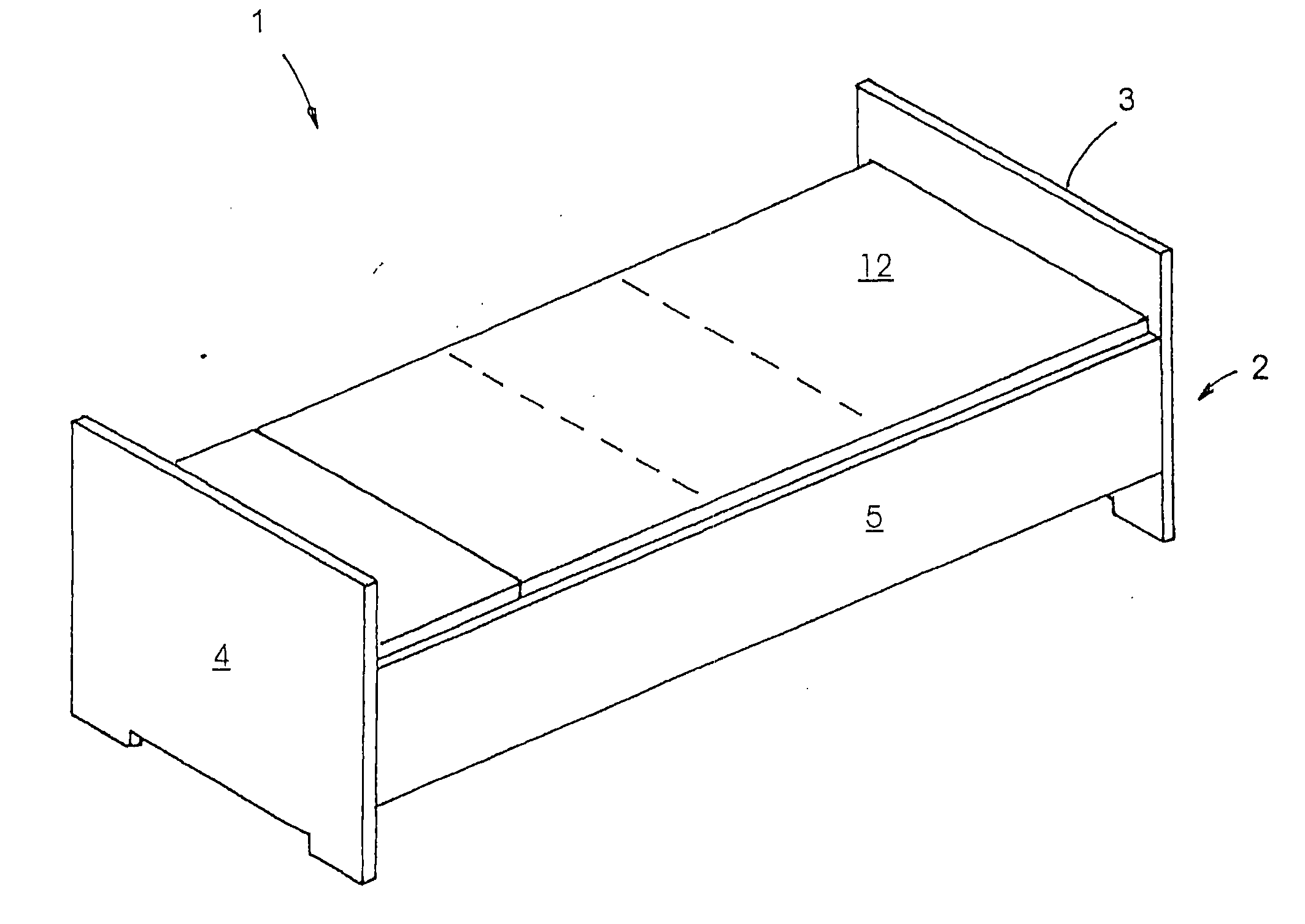
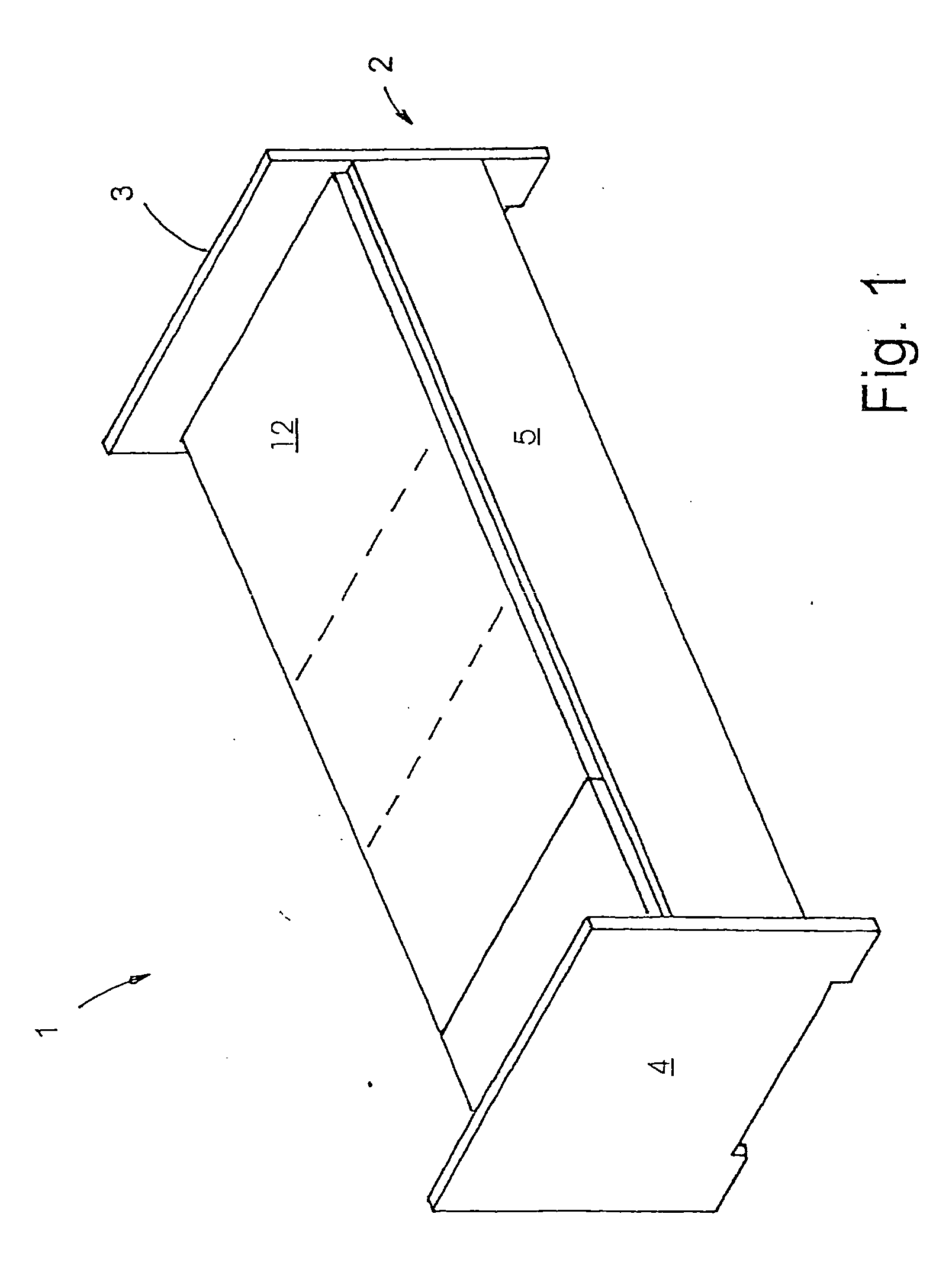
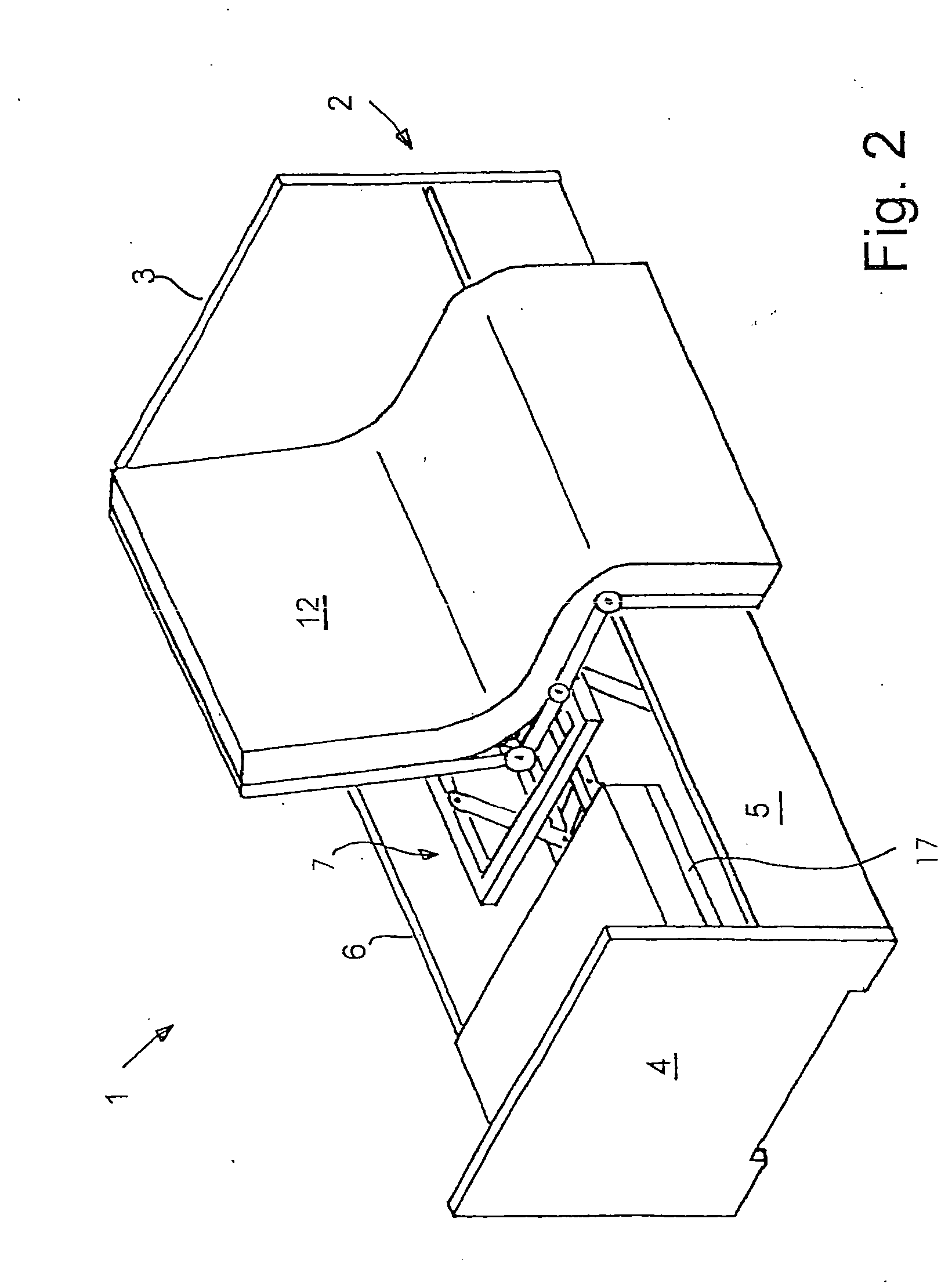
[0019] Referring to FIGS. 1 and 2 of the drawings, an illustrative nursing bed 1 according to the invention is shown in the reclined position (FIG. 1) and in the sitting or chair position (FIG. 2). The nursing bed 1 includes a bed frame 2 with a head part 3, a foot part 4 as well as side walls 5 and 6. The outward facing side wall 5 (with reference to FIGS. 1 and 2) is in the raised position as reflected by the distance of the side wall 5 from the floor. The gap between the underside of the side wall 5 and the floor enables the nursing personnel to place the forward section of their feet underneath the bed. The side wall 5 is movably supported and displaced downward in the chair position of the nursing bed 1 as shown in FIG. 2. The support of the side wall 5 is explained in detail, for example, in DE 199 12 937 A1, the disclosure of which is incorporated herein by reference.

[0020] A bed lifting mechanism 7 is situated within the bed frame 2 as shown in FIG. 3. The bed lifting mecha...


PUM


Abstract

A height-adjustable nursing bed is provided that includes a pedestal in which the upper frame and the lower frame are connected to one another by a total of four toggle lever pairs. The toggle lever pairs on each side of the bed are additionally connected to one another by horizontally and diagonally extending coupling braces. The horizontal coupling brace connects the toggle levers in the region of the toggle link while the diagonal coupling brace connects a lower toggle lever arm to an upper toggle lever arm. The motor for raising and lowering the upper frame relative to the lower frame extends directly between these two frames such that the toggle levers and their coupling braces act as a parallel linkage of sorts.

Description

BACKGROUND OF THE INVENTION [0001] A lifting mechanism for a nursing bed is described in DE 198 54 136 A1. The disclosed lifting mechanism included a frame that forms the pedestal of the lifting mechanism, as well as an upper frame that is arranged approximately congruent with the frame and serves as the lifting head. A total of four levers are provided in the side of the lifting mechanism. Two of the levers are respectively connected to one another by a toggle link. At the toggle links, two toggle lever pairs are kinematically connected to one another by a horizontal coupling brace. Another coupling brace connects one of the upper levers to a lower lever on each side, for example, the upper lever at the foot end of the bed to the lower lever at the head end. One end of the driving motor for moving the lifting mechanism engages a cross brace of the pedestal and the other end engages a connecting brace that connects the two horizontally extending coupling braces to one another. [0002...

Claims


Application Information

Patent Timeline
Patent Type & Authority Applications(United States)
IPC IPC(8): A47B7/02A47C19/04A47C20/08A61G7/012A61G7/015A61G7/053A61G7/10
CPCA47C19/045A47C20/041A47C20/08A61G7/012A61G2200/34A61G7/053A61G7/1076A61G7/16A61G2200/32A61G7/015
Inventor BARTHELT, HANS-PETER
Owner BARTHELT HANS PETER
Why Eureka
Try Eureka