Front-accessible bevel locking system

a technology of bevel locking and front access, which is applied in the field of tilt locking mechanisms for power tools, can solve the problems of inaccessible location of conventional bevel locking mechanisms, inconvenience and threat to the safety of users of conventional power tools, and achieve the effect of increasing or decreasing the pressure applied and increasing the tension

Inactive Publication Date: 2007-08-02
CREDO TECH CORP
View PDF31 Cites 13 Cited by
  • Summary
  • Abstract
  • Description
  • Claims
  • Application Information

AI Technical Summary

Benefits of technology

[0015] The second embodiment also includes a lever stop mounted to the cam pin (on the cam axis) on a side of the cam follower away from the bevel lock lever. The lever stop hits the worktable when the bevel lock lever rotates the cam pin beyond a certain angle in either a clockwise or a counter-clockwise direction so that the bevel lock lever does not hang loose when not in the locked position.
[0016] Finally, the second embodiment also includes a combination of flanged nut and lock nut at the end of the link rod of the second embodiment. The lock nut can be adjusted to move the flange nut either closer to the outside plate of the pivot support housing or further away, effectively increasing or decreasing the pressure applied to the pivot support housing when the bevel lock lever is moved into the locked position. The flanged nut may also have two layers, with a first layer closest to the outside plate of the pivot support housing having a compressible material specially adapted to increase the tension between the pivot support housing and the flanged nut.

Problems solved by technology

However, there is a significant disadvantage to conventional methods in that conventional bevel locking systems have been generally located at the rear and of a cutting tool, away from a user.
The inaccessible location of conventional bevel locking mechanisms is both an inconvenience and a threat to user safety: these are significant disadvantages to heavy users of a conventional power tool, such as a miter saw.

Method used


Image

  • Front-accessible bevel locking system
  • Front-accessible bevel locking system
  • Front-accessible bevel locking system

Examples


Embodiment Construction

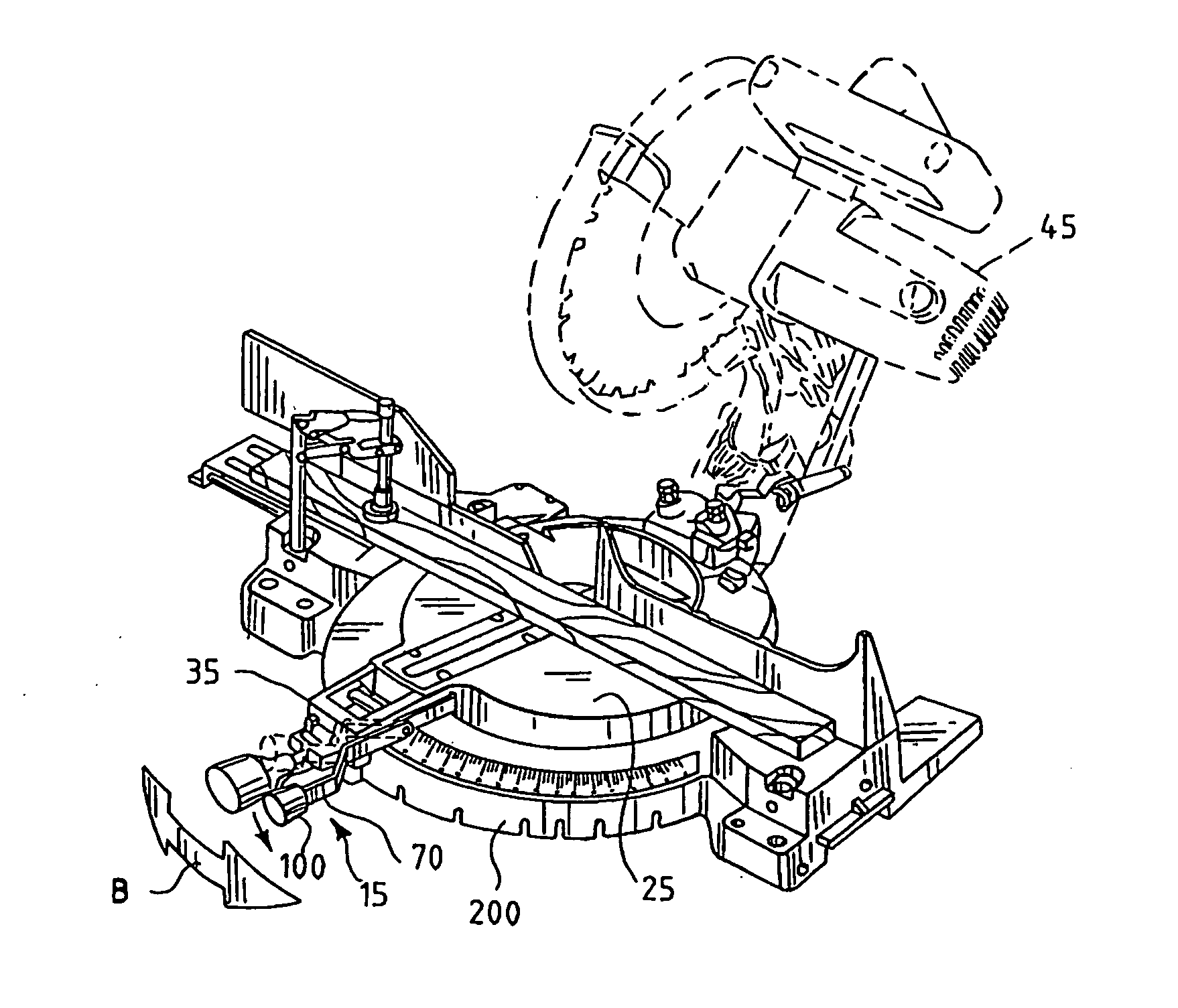
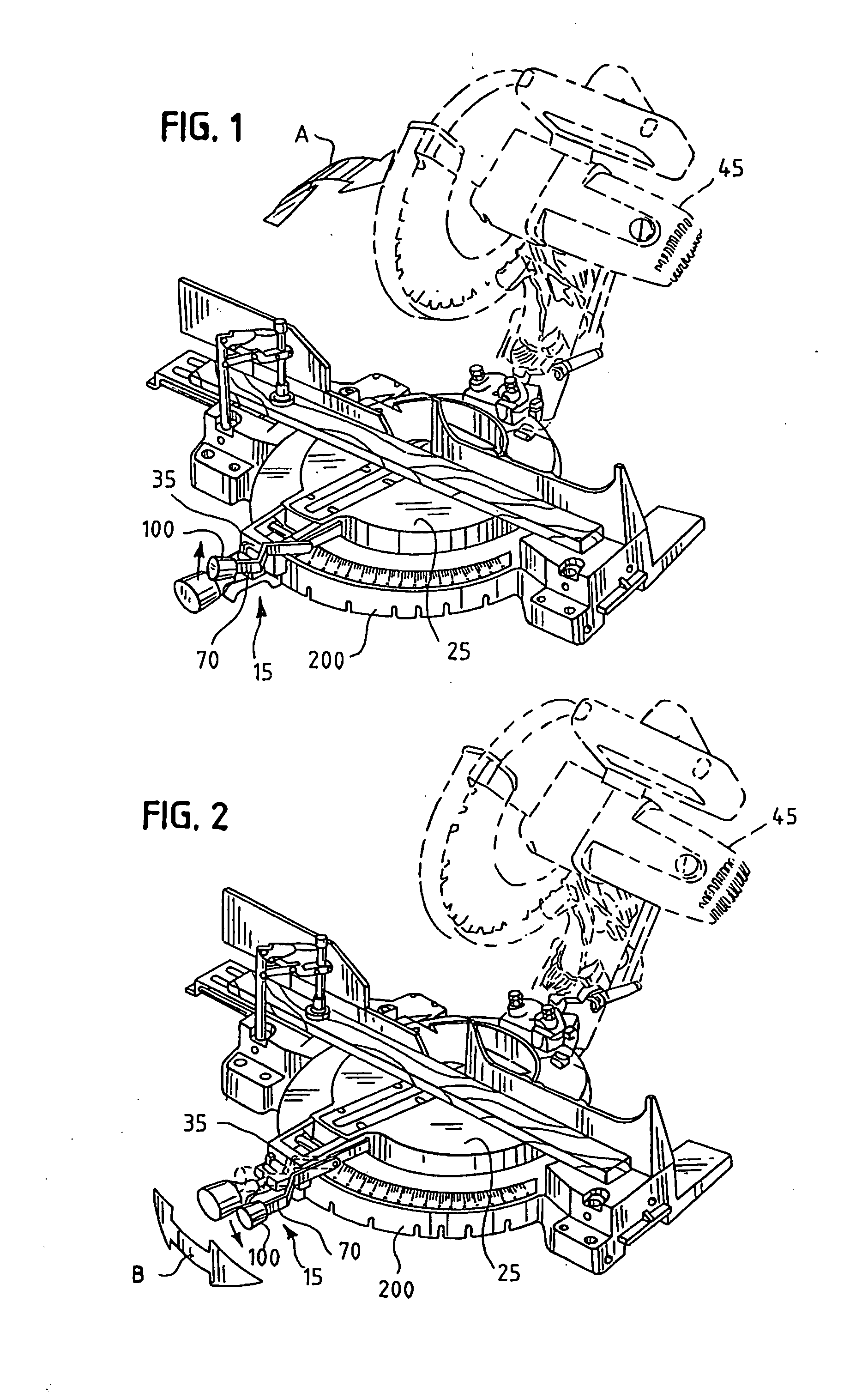
[0033] In all of the embodiments shown in the figures, the invention is provided in a dual bevel compound miter saw. However, as will be recognized by those of skill in the art, there is nothing to prevent the invention as described and disclosed herein from being incorporated in a different power tool in which there is also an advantage to be gained by providing a tilt or bevel angle locking system accessible from the front end of the power tool.

[0034]FIGS. 1-2 provide a general understanding of how a bevel locking system functions to hold a tilt or bevel angle for a power tool. In FIGS. 1-2, there is illustrated, in accordance with a first embodiment of the present invention, a bevel locking system 15 for holding a power tool 45 at a selected bevel or tilt angle for making a bevel cut. The movement of the power tool 45 along the bevel or tilt angles is indicated by a curved arrow A in FIG. 1. When the bevel lock lever 70 is unlocked, as in the embodiment shown in FIG. 1, the powe...


PUM

PropertyMeasurementUnit
angleaaaaaaaaaa
acute angleaaaaaaaaaa
angleaaaaaaaaaa

Abstract

A front-accessible bevel locking system for use with a power tool includes a mechanism for locking the power tool into a selected tilt or bevel position for bevel angle cuts. The bevel locking mechanism has a lever attached to a link rod by a cam mechanism such that, as the lever is moved to the locked position, the link rod holds a pivot support for the power tool at a bevel angle.

Description

[0001] This application is a continuation of co-pending application Ser. No. 10 / 271,512, filed on Oct. 16, 2002 (Patent Application Publication No. U.S. 2004 / 0074362 A1). The disclosure of the above-identified patent application is hereby totally incorporated by reference in its entirety.FIELD OF THE INVENTION [0002] The present invention relates generally to tilt locking mechanisms for power tools, and more specifically, to a bevel locking system accessible from the front side of a power tool, which is capable of holding the power tool in a tilted position for bevel angle cuts. BACKGROUND OF THE INVENTION [0003] Many power tools, such as mills, drill presses, or miter saws, are capable of producing a cut or hole to a work piece placed against a horizontal table beneath a power drill or saw. Some power tools, such as miter saws, have a rotatable horizontal table for making vertical cuts to a work piece at various angles. A vertical cut made at such an angle is called a “miter cut”. ...

Claims


Application Information

Patent Timeline
Patent Type & Authority Applications(United States)
IPC IPC(8): B23D45/04B27B5/29
CPCB27B5/29B23D45/044Y10T83/7697Y10T83/7705Y10T83/7726Y10T83/7788Y10T83/8773
Inventor SVETLIK, KENNETHROMO, EZEQUIELLIAO, YI-TEHUANG, CHIH-YUNG
Owner CREDO TECH CORP
Why Eureka
Try Eureka