Hands free device for filling tanks

a technology for filling tanks and hands, which is applied in the direction of liquid transfer devices, liquid handling, packaging goods types, etc., can solve the problems of tank overflow, tank or fill neck rupture, tank damage, etc., and achieve the effect of preventing damage to the fill neck or other components, water waste, and preventing damage to the tank

Active Publication Date: 2007-08-02
VALTERRA PRODS
View PDF11 Cites 4 Cited by
  • Summary
  • Abstract
  • Description
  • Claims
  • Application Information

AI Technical Summary

Benefits of technology

[0004]The present invention relates to novel devices and methods of filling tanks designed for holding non-hazardous fluids, especially tanks on, for example, recreational vehicles (RV). Non-limiting examples of suitable vehicles are motor homes, campers or boats, or concession trailers, food service trailers, etc. In a preferred embodiment, the tank to be filled is a water tank. The device of the present invention incorporates several novel and non-obvious features to create a device that permits the filling of tanks in a hands-free manner while keeping water waste to a minimum and preventing damage to the tank, fill neck or other components due to the over filling of the tank.
[0005]In one embodiment, the device of the present invention enables a hose (e.g., an RV fresh water hose or garden hose) to be securely fastened to the fresh water fill spout on an RV for water tank filling purposes and controls the gallons per minute of water to prevent damage to the tank or other components.
[0011]The device of the present invention may also have a shut off valve incorporated into the device. The shut off valve permits the operator to start and stop the flow of the fluid (e.g., water) without having to travel back and forth to the source to start and stop the flow. In a preferred embodiment the valve is a ball valve but the device is not limited to any particular type of valve as long as the valve will control the flow of the fluid and is compatible with the fluid (i.e., it will not corrode or degrade appreciably when exposed to the fluid).
[0015]In one embodiment, the screw cap-type or twist cap-type fitting (or other suitable, compatible fitting) for attaching the device of the present invention to the fill neck of the tank to be filled also comprises one or more vent holes. The vent holes are sized to permit air to exit the tank as it filled with fluid (e.g., water). In another embodiment, the vent holes are sized to allow the egress of the fluid in the event the tank is filled and the fluid supply is not shut off. Thus, in a preferred embodiment, the vent holes permit at least the same rate of fluid flow (gallons per minute) or greater as the self-regulating flow device of the present invention. This embodiment ensures that the tank will not become damaged if the fluid supply is, for example, inadvertently left on after the tank is full since the fluid will have an means for exiting the tank that will permit the egress of the fluid at a rate comparable to the rate of fluid flow into the tank.
[0021]In a preferred embodiment, the device of the present invention enables a garden hose to be securely fastened to the fresh water fill spout on an RV (recreational vehicle) for the water tank filling purposes and controls the gallons per minute of water to keep from damaging the tank.

Problems solved by technology

If the process is not watched carefully (for example, the person leaves to do something else), the hose may slip out wasting water and creating a mess, the tank may overflow or, if something has been used to keep the hose from slipping out, the tank or fill neck may rupture or other equipment (such as a gauge mechanism located in the tank) may be damaged.

Method used


Image

  • Hands free device for filling tanks
  • Hands free device for filling tanks
  • Hands free device for filling tanks

Examples


Embodiment Construction

[0030]The invention will now be described in detail with reference to a few preferred embodiments, as illustrated in accompanying drawings. In the following description, numerous specific details are set forth in order to provide a thorough understanding of the invention. However, it will be apparent to one skilled in the art that the invention may be practiced without some or all of these specific details. In other instances, well-known features and / or process steps have not been described in detail in order to not unnecessarily obscure the invention. The features and advantages of the invention may be better understood with reference to the drawings and discussions that follow.

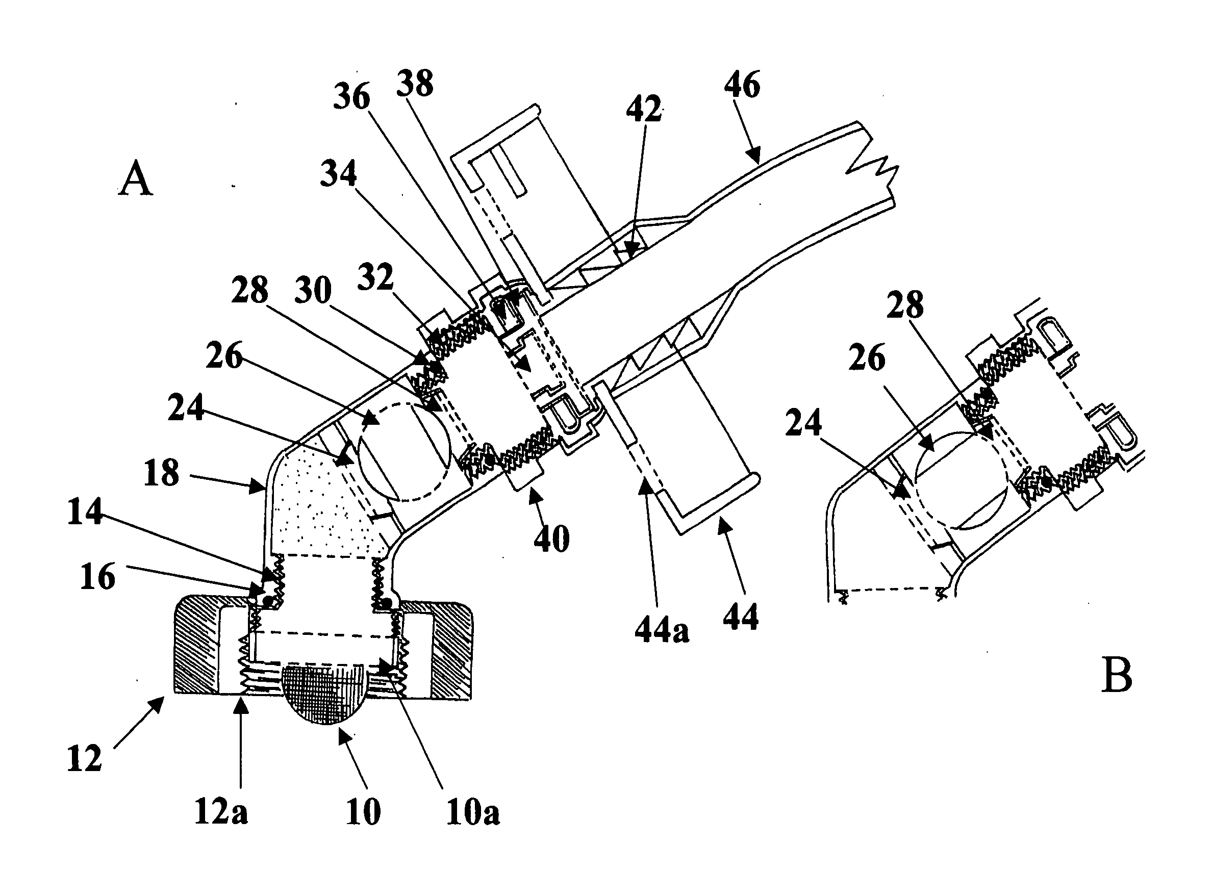
[0031]In the present invention, the terms “fill spout,”“fill neck,”“fill port” and “tank neck,”“tank spout” and “tank port,” and the like, are equivalent terms and refer to the portion of the tank wherein a fluid is added to the tank.

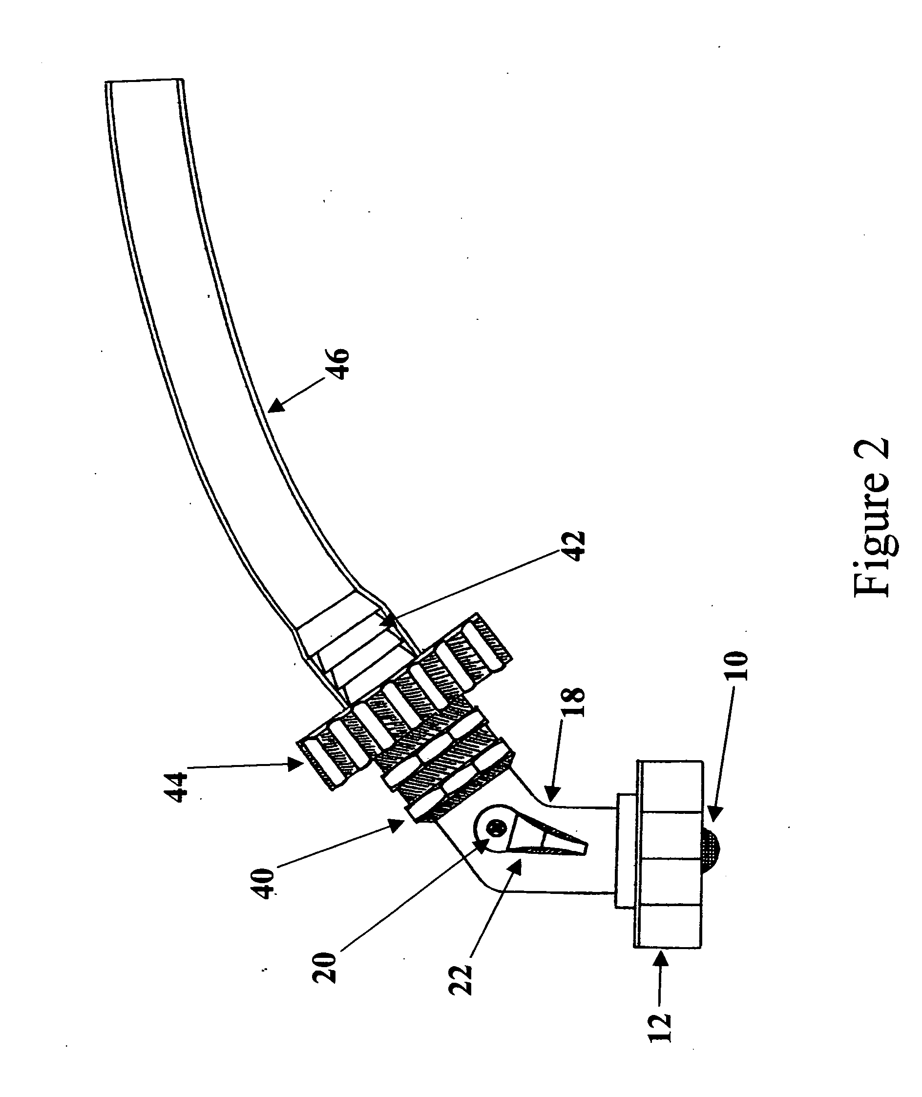
[0032]Referring now to FIG. 2, the device of the present invention comprise...


PUM

PropertyMeasurementUnit
diameteraaaaaaaaaa
diameteraaaaaaaaaa
pressureaaaaaaaaaa

Abstract

The present invention relates to novel devices and methods of filling tanks designed for holding non-hazardous fluids, especially tanks on recreational vehicles. In a preferred embodiment, the tank to be filled is a water tank. The device of the present invention incorporates several novel and non-obvious features to create a device that permits the filling of tanks in a hands-free manner while keeping water waste to a minimum and preventing the damaging of tank, fill neck or other tank or fill components due to the over filling of the tank.

Description

STATEMENT OF PRIORITY[0001]This Application claims the benefit of Provisional Application No. 60 / 763,447, filed Jan. 30, 2006.BACKGROUND OF INVENTION[0002]A recreational vehicle such as a motor home, camper or boat, or concession trailers, food service trailers, etc., must, by necessity, carry everything the occupants need onboard. This means that food, water and waste is carried on the vehicle until the occupants are able to re-supply provisions and discard the wastes. Food is physically carried onboard, dry waste is carried out while wet waste is pumped or drained into appropriate sanitation facilities. Water must be transported in one or more tanks on the vehicle and must be refilled as required. Traditionally, water tanks on a recreational vehicle are filled with a hose. The end of the hose is placed into the fill neck of the tank while the person filling the tank holds the hose and waits for the tank to fill. If the process is not watched carefully (for example, the person leav...

Claims


Application Information

Patent Timeline
Patent Type & Authority Applications(United States)
IPC IPC(8): B65B1/04
CPCB67D7/0294B60R15/00
Inventor RAY, ANDREW G.
Owner VALTERRA PRODS
Why Eureka
Try Eureka