Automated toilet paper dispenser

a dispenser and automatic technology, applied in the field of paper dispensers, can solve the problems of toilet paper waste, theft, and unwinding the entire roll, and achieve the effects of reducing the number of rolls

Inactive Publication Date: 2007-08-02
DISPENSING DYNAMICS INT
View PDF24 Cites 56 Cited by
  • Summary
  • Abstract
  • Description
  • Claims
  • Application Information

AI Technical Summary

Benefits of technology

[0012] The drive roller can be positioned in the housing to engage a leading edge of the roll. When the roll is perforated, a secondary pair of pinch rollers can be provided to grip the leading edge of the roll and prevent perforations in the leading edge of the roll from breaking about the drive roller. When the roll is non-perforated, severing means like a knife can be provided to sever a dispensed portion from the roll.

Problems solved by technology

A common concern in providing toilet paper in public facilities is wastage and theft of toilet paper.
Worse, abuse can occur by unwinding the entire roll and stealing the paper, or leaving the paper unused and wasted.
Another problem with known toilet paper dispensers is that users typically have to reach under the dispensers to grab the leading edge of the toilet paper roll, then pull the leading edge downwards in order to extract paper from the dispenser.
This can be an awkward process, especially if the dispenser is mounted low, or if there is an insufficient tail protruding under the dispenser for the user to obtain a firm grip.
Persons with disabilities or restricted mobility can find operating such dispensers to be particularly challenging.
Sometimes when the paper is particularly fragile or when the roll is difficult to rotate, the paper segment separates from the roll by the downwards pull by the user, leaving the user with a much shorter portion than intended.
However, many users are reluctant to touch the dispenser, as such dispensers can be dirty and can contain bacteria or other unhygienic material.

Method used


Image

  • Automated toilet paper dispenser
  • Automated toilet paper dispenser
  • Automated toilet paper dispenser

Examples


second embodiment

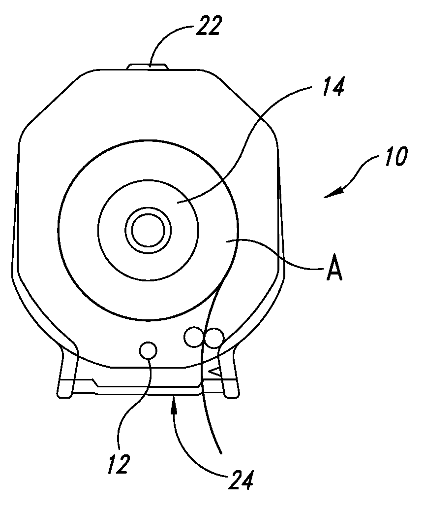
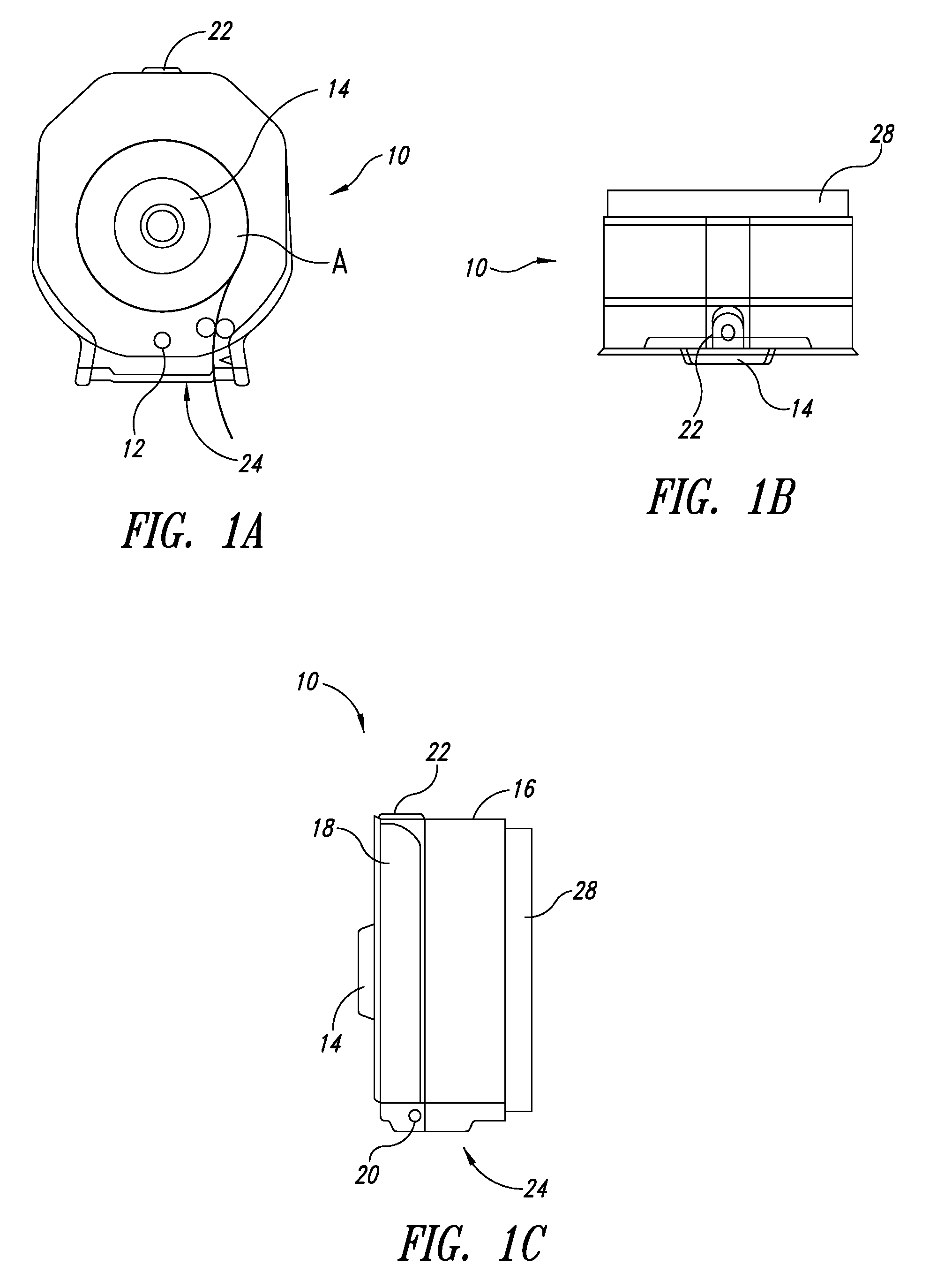
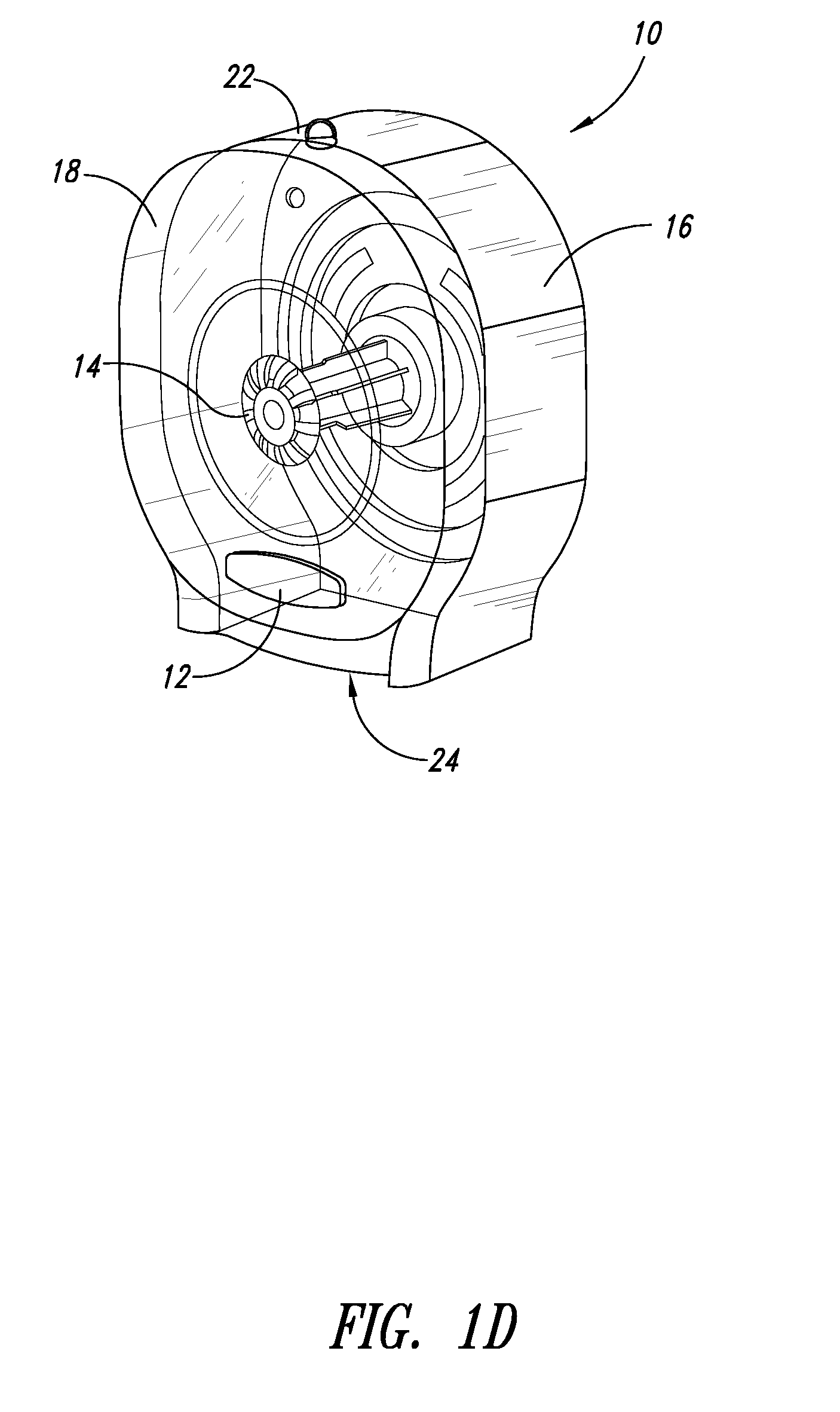
[0041] Referring to FIGS. 4(a)-(d) and 5 and according to the invention, the automated dispensing assembly of the dispenser 10 is modified so that the rollers 30, 34 are replaced by a drive roller 100 which is in direct contact with the surface of the paper roll A. The drive roller 100 has an axle 102 that is movably mounted to the housing 16 and is biased against the paper roll A such that the drive roller 100 is always in contact with the roll A regardless of the roll's size. The axle 102 extends through a track 104 in the housing 16 and is weighted at one end so that gravity biases the drive roller 100 downwards through the track 104 and against the roll A. Alternatively, the drive roller 100 can be biased using springs or other biasing means known in the art.

first embodiment

[0042] The surface of the drive roller 100 has a sufficient coefficient of friction to rotate the roll A when the motor 26 rotates the drive roller 100. The motor 26 is also movably mounted along the track 104 and is rotationally coupled to the drive roller 100 using the one way bearing and gears as described in the Alternatively, the motor 26 can be fixed to the housing 26 and rotationally coupled to the drive roller 100 using a series of gears and chain as is well known in the art (not shown).

[0043] Like the first embodiment, the drive roller 100 is coupled to the motor 26 by the one way bearing 36. Therefore, a user can manually operate the dispenser 10 either by pulling on the leading edge of the roll A, or turning the knob of the manual dispensing assembly 14, or both.

third embodiment

[0044] Referring to FIGS. 6(a)-(c) and 7 and according to the invention, the automated dispensing assembly of the dispenser 10 is modified so that the support 32 is rotatably coupled to the housing 16, and is driven by the motor 26. In other words, the support 32 acts as a drive roller, and is coupled to the motor 26 by the one way bearing and reduction gears as described in the previous embodiments. Like in the previous embodiments, the knob 14 is provided on the door 18 and is coupled to the support 32 such that rotation of the knob 14 by the user causes the support 32 to rotate and paper to be manually dispensed, whether or not the motor 26 is operating.

[0045] Because the roll A diameter diminishes as paper is dispensed, the length of toilet paper dispensed is not constant relative to the number of rotations of the roll support 32. Therefore, the dispenser 10 in this embodiment is provided with a roller sensor 50 which is in contact with the leading edge of the roll A. The contro...


PUM


Abstract

A toilet paper dispenser is provided that is operable in an automatic dispensing mode and a manual dispensing mode. The dispenser comprises a housing for containing a toilet paper roll; a drive roller engagable with the roll; a motor; and a one-way coupling that couples the motor to the drive roller in a first direction to automatically dispense paper from the dispenser and decouples same in an opposite second direction, thereby enabling toilet paper to be manually dispensed in the first direction.

Description

CROSS-REFERENCE TO RELATED APPLICATION [0001] This application is a continuation-in-part of U.S. patent application Ser. No. 11 / 423,100, filed on Jun. 8, 2006, now pending, which is a continuation-in-part of U.S. patent application Ser. No. 11 / 245,585, filed on Oct. 7, 2005, now pending, where these two applications are incorporated herein by reference in their entireties.FIELD OF THE INVENTION [0002] This invention relates generally to paper dispensers and particularly to away-from-home type toilet paper dispensers. BACKGROUND OF THE INVENTION [0003] A common concern in providing toilet paper in public facilities is wastage and theft of toilet paper. Known toilet paper dispensers, whether single roll or double roll, dispense a user-selectable portion of the toilet paper roll stored in the dispenser. The toilet paper roll may be perforated, in which case the user unwinds a desired number of perforated segments from the roll then tears the segments away from the roll along one of the...

Claims


Application Information

Patent Timeline
Patent Type & Authority Applications(United States)
IPC IPC(8): B65H26/00
CPCB65H16/06B65H16/005B65H26/06B65H16/106
Inventor FRIESEN, JOHNFRIESEN, BRADFRIESEN, MATTHEW
Owner DISPENSING DYNAMICS INT
Why Eureka
Try Eureka