
Device control apparatus

a technology of device control and control apparatus, applied in the direction of instrumentation, data switching network, electric programme control, etc., can solve the problem of cost-effective creation of individual applications to conform

Active Publication Date: 2007-08-02
PANASONIC CORP
View PDF3 Cites 15 Cited by
  • Summary
  • Abstract
  • Description
  • Claims
  • Application Information

AI Technical Summary

Benefits of technology

[0019] As clearly shown in the aforementioned explanation, in the present invention of the device control apparatus, a device to be controlled is identified, based not only on the specification, but also on the use situation of the device. As such, it is possible to appropriately identify a device that can achieve a purpose of an application.
[0020] Furthermore, in the present invention of the device control apparatus, a condition for identifying a device to be controlled can be changed without modifying the application. Moreover, in the application of the present invention, the device is abstracted from a viewpoint of whether or not the device can carry out a specific role. Therefore, it becomes possible to change, without modifying the application, a specification condition which a device to be operated should be equipped with.

Problems solved by technology

However, normally, the combination of home appliances owned by a user of the application is different for each user, and it is costly to create individual applications to conform to each user.

Method used


Image

  • Device control apparatus
  • Device control apparatus
  • Device control apparatus

Examples


first embodiment

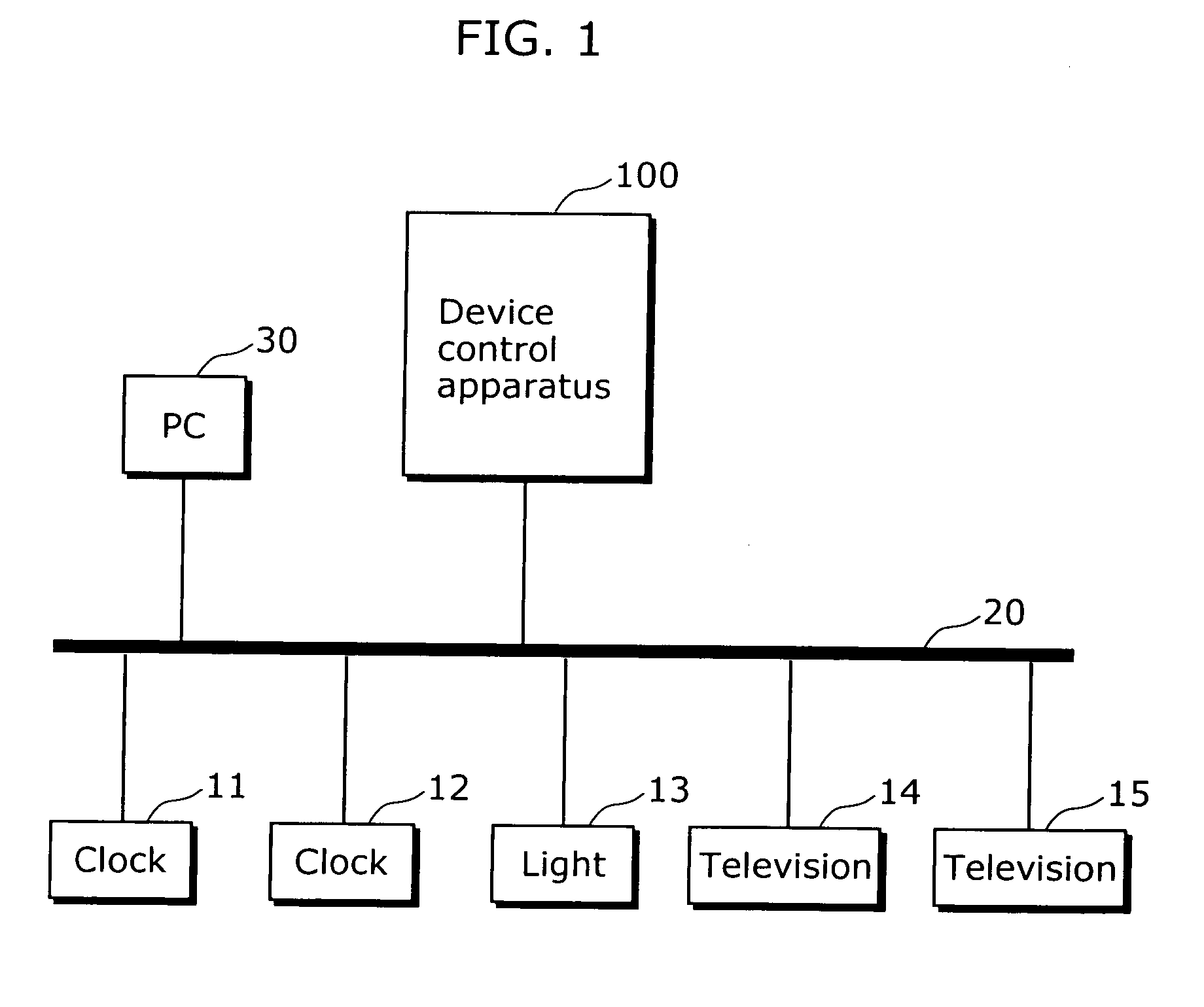
[0050]FIG. 1 is a diagram showing the use environment of a device control apparatus 100 in the first embodiment of the present invention. Here, the status is shown where a clock 11, a clock 12, a light 13, a television 14, a television 15, a personal computer (PC) 30, and a device control apparatus 100 in the home are connected via a network 20. The network 20 may be a wireless network using a wireless communication protocol, such as the Bluetooth and the like, or a wired network, such as a power line network and the like.

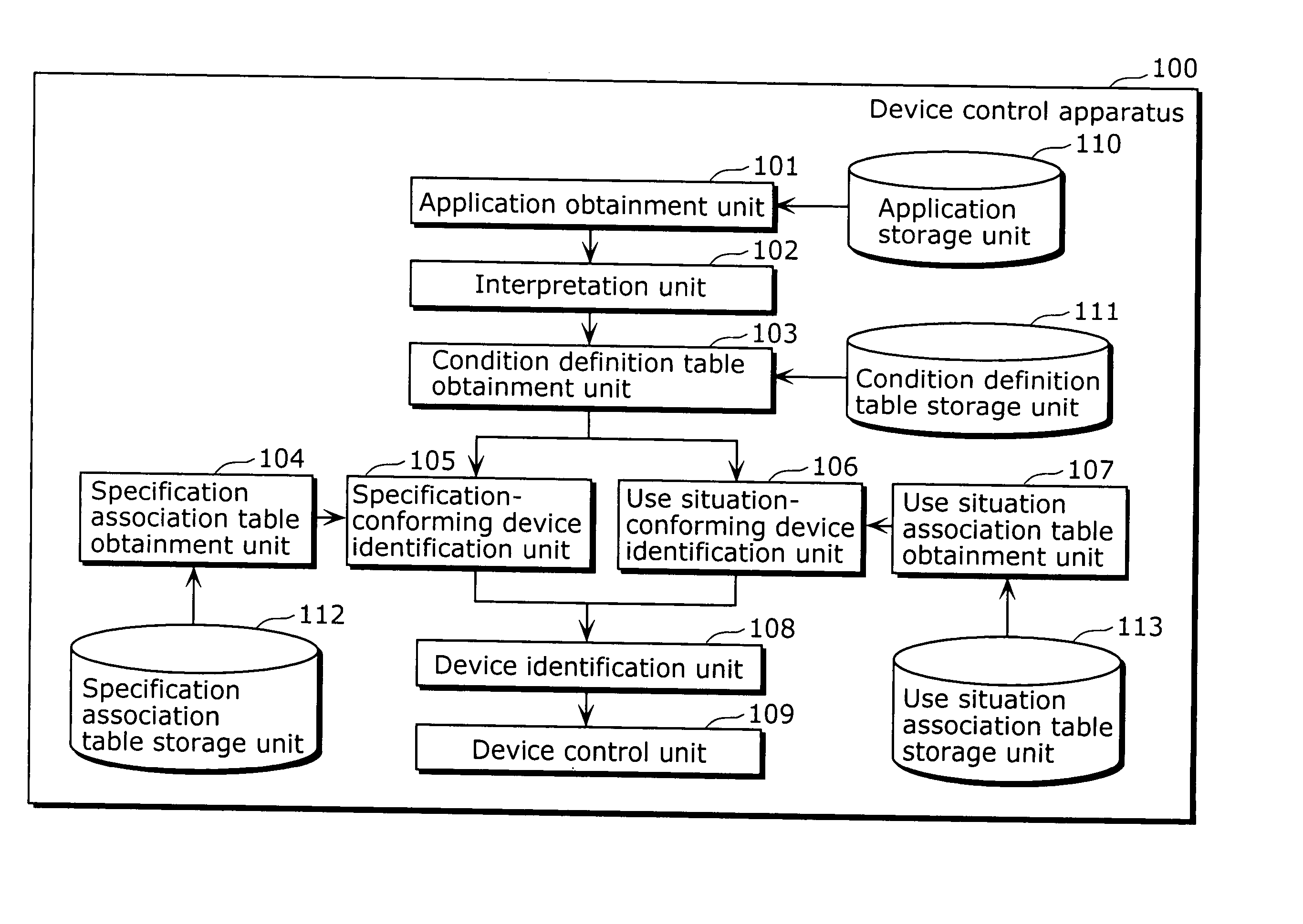
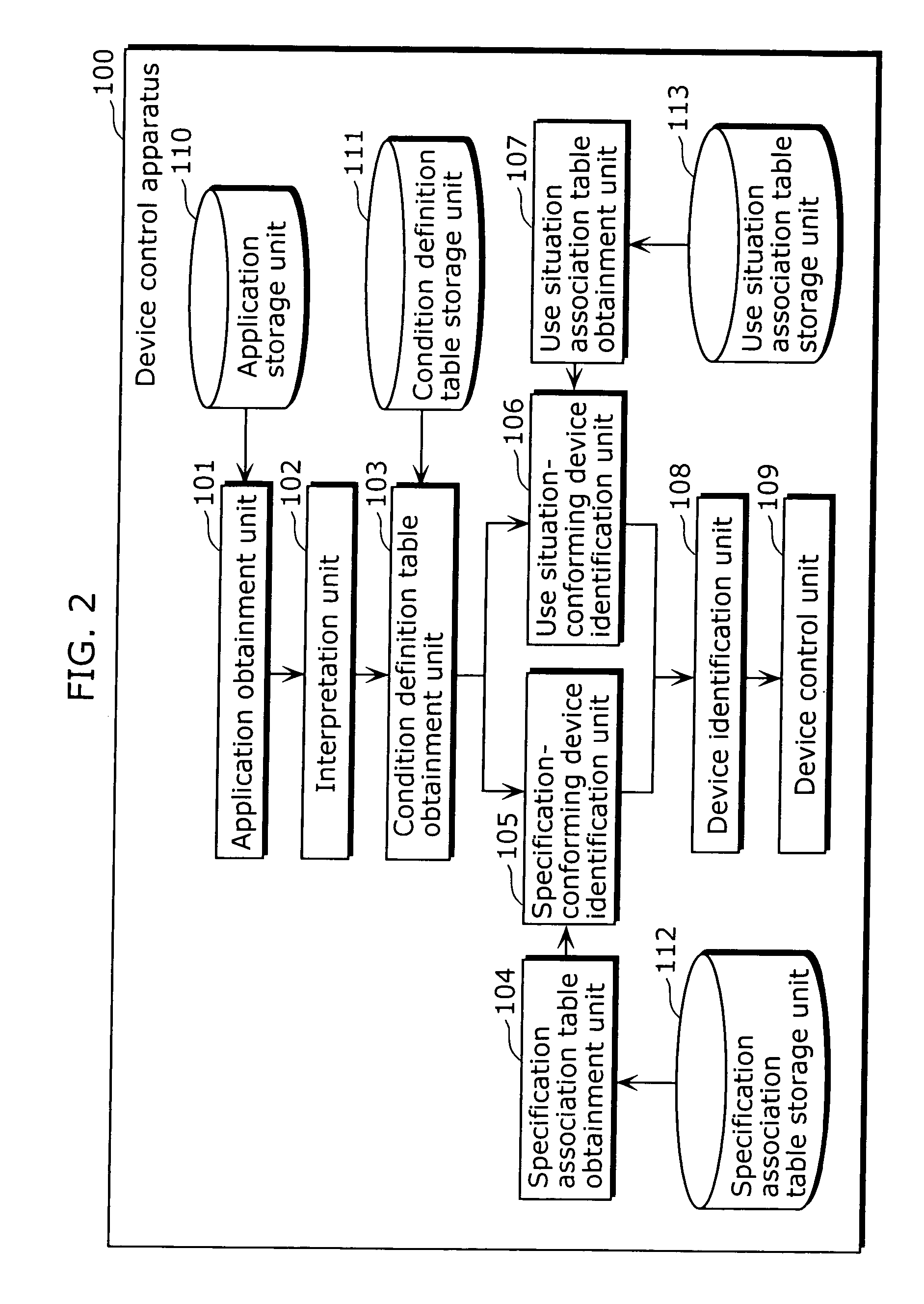
[0051] The device control apparatus 100 is an apparatus for controlling the devices 11 to 15 to operate in linkage with each other. In other words, by obtaining information from the devices 11 to 15, processing the obtained information, and providing the processed information to the devices 11 to 15, the devices 11 to 15 are controlled to operate in linkage with each other. However, the details of the linked operation are not particularly limited, as it depends on...

second embodiment

[0081] The first embodiment of the present invention is described, on the premise that the specification condition and the use situation condition are defined in the condition definition table in advance. In the second embodiment of the present invention, a technique which changes the details of the condition definition table is described.

[0082]FIG. 8 is a diagram of the structure of the device control apparatus 100 in the second embodiment of the present invention. In addition to the structure described in the first embodiment of the present invention, this device control apparatus 100 is equipped with a condition change unit 120.

[0083] The condition change unit 120 changes the details of the condition definition table stored in the condition definition table storage unit 111. The method which issues a command to the condition change unit 120 is not particularly limited, and for example, a method using the personal computer 30, which is connected to the device control apparatus 1...


PUM


Abstract

The present invention is aimed at appropriately identifying a device which can achieve a purpose of an application. A device control apparatus (100) according to the present invention includes: a specification-conforming device identification unit (105) which identifies a device which conforms to a specification-related condition that should be satisfied by a device with an abstract name described in the application; a use situation-conforming device identification unit (106) which identifies a device which conforms to a use situation-related condition that should be satisfied by a device with an abstract name described in the application; and a device control unit (109) which controls, based on the application, the device identified by both the specification-conforming device identification unit (105) and the use situation-conforming device identification unit (106).

Description

TECHNICAL FIELD [0001] The present invention relates to an apparatus which controls a plurality of devices, and particularly to an apparatus which controls a plurality of home appliances to operate in linkage with each other. BACKGROUND [0002] In recent years, by controlling appliances in a home to operate in linkage with each other, systems for providing various services have been proposed. These systems are realized by executing an application program (hereinafter referred to simply as “application”) for controlling a plurality of devices to operate in linkage with each other. [0003] In general, information which specifically identifies the home appliances to be controlled to operate in linkage with each other is described in the application. However, normally, the combination of home appliances owned by a user of the application is different for each user, and it is costly to create individual applications to conform to each user. Therefore, there is a method which expands the ve...

Claims


Application Information

Patent Timeline
Patent Type & Authority Applications(United States)
IPC IPC(8): G05B19/02
CPCH04L12/2803H04L12/282H04L2012/285H04L2012/2843H04L2012/2849H04L2012/2841
Inventor YAMAMOTO, KAKUYA
Owner PANASONIC CORP
Learn More