Display device, terminal device, and display panel
a terminal device and display panel technology, applied in static indicating devices, non-linear optics, instruments, etc., can solve the problems of not improving the viewing angle characteristics, not allowing private and confidential information, and reducing the size and cost of controlling scattering
- Summary
- Abstract
- Description
- Claims
- Application Information
AI Technical Summary
Benefits of technology
Problems solved by technology
Method used
Image

Examples
first embodiment
[0102] A display device 2 is composed of a light source device 1 and a transmissive LCD panel 7, as shown in FIG. 4. A light-guide plate 3 comprising a transparent material is disposed in the light source device 1, and the shape of the light-guide plate 3 is that of a rectangular plate. A light source is disposed in a position facing one side surface (light-incident surface 3a) of the light-guide plate 3. The light source is a white LED (Light Emitting Diode) 51, for example. A plurality of white LEDs 51 is disposed along the light-incident surface 3a of the light-guide plate 3, and the number of LEDs is five, for example. In the light-guide plate 3, light inputted from the light-incident surface 3a is uniformly emitted from the main surface (light-excident surface 3b).
[0103] An optical film 4 is disposed on the light-excident surface 3b side of the light-guide plate 3. The optical film 4 is used for deflecting light emitted from the light-guide plate 3 toward the normal direction ...
second embodiment
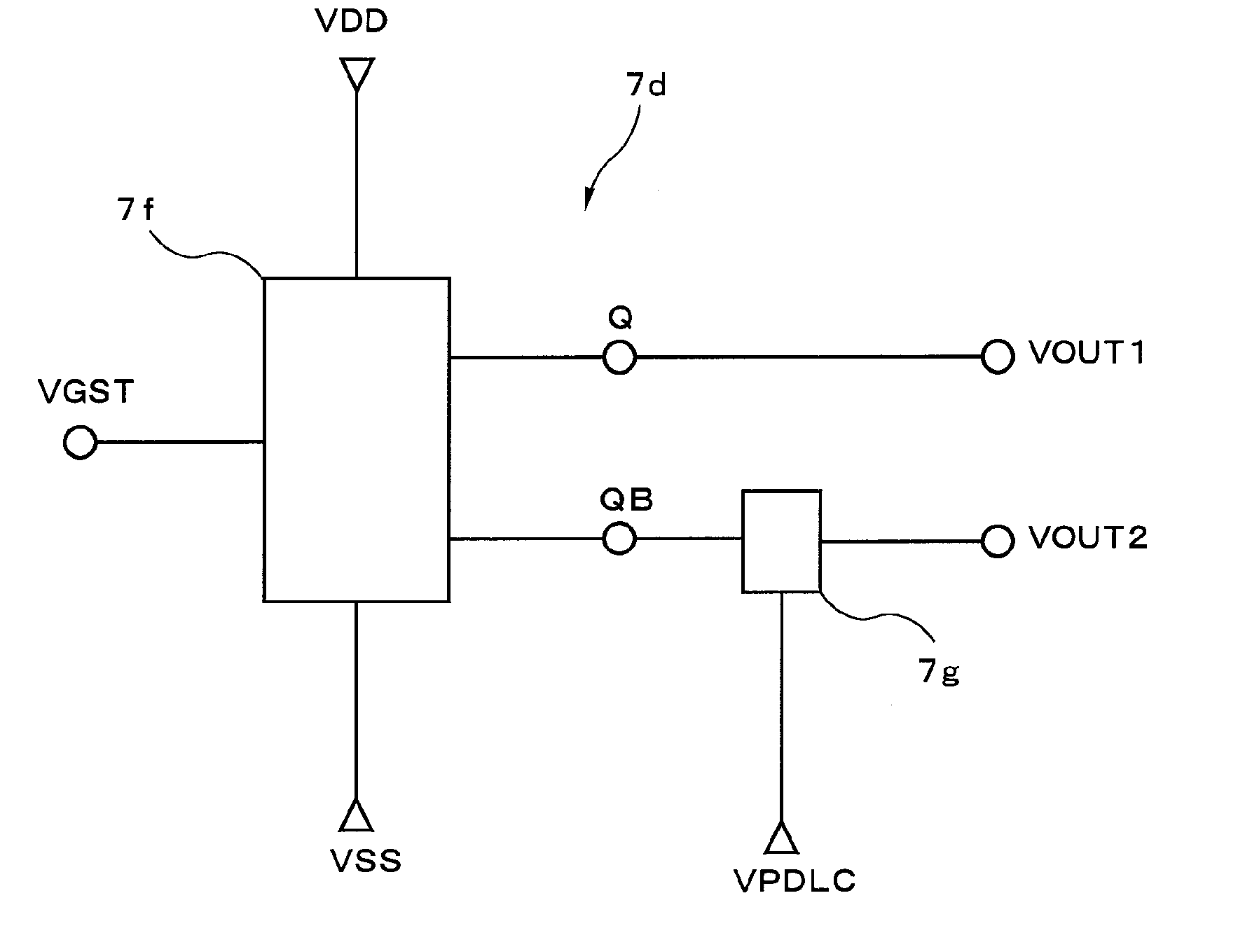
[0142] the present invention is described next. FIG. 11 is a perspective view showing the display device according to the present embodiment of the present invention. FIG. 12 is a top view showing the configuration of a transmissive LCD panel, which is a constituent element of the display device. FIG. 13 is a circuit diagram of the transparent / scattering switching element drive circuit used for driving the transparent / scattering switching element.
[0143] The display device 21 according to the second embodiment is composed of a light source device 1 and a transmissive LCD panel 71, as shown in FIG. 11. In the transmissive LCD panel 71, a transparent / scattering switching element drive circuit 71d is used in place of the transparent / scattering switching element drive circuit 7d, as shown in FIGS. 12 and 13, in comparison with the transmissive LCD panel described in the first embodiment described above. A 1-bit counter circuit 7f was used in the transparent / scattering switching element d...
third embodiment
[0148] the present invention is described next. FIG. 15 is a perspective view showing the display device according to the present embodiment. FIG. 16 is a perspective view showing a louver, which is constituent element of the display device and which is an element that restricts the direction of light beams.
[0149] The display device 22 according to the present third embodiment features the use of a louver 112, which is a constituent element in the form of a light direction restricting element, as shown in FIG. 15, in comparison with the display device 2 according to the first embodiment described above. The louver 112 is disposed between the optical film 4 and the transparent / scattering switching element 122.
[0150] The louver 122 has light-transmitting transparent areas 112a and light-absorbing absorption areas 112b, and these areas are disposed in an alternating fashion in the direction parallel to the louver surface, as shown in FIG. 16. The direction in which the transparent and...
PUM
 Abstract
Description
Claims
Application Information
 - R&D
- Intellectual Property
- Life Sciences
- Materials
- Tech Scout
- Unparalleled Data Quality
- Higher Quality Content
- 60% Fewer Hallucinations
Browse by: Latest US Patents, China's latest patents, Technical Efficacy Thesaurus, Application Domain, Technology Topic, Popular Technical Reports.
© 2025 PatSnap. All rights reserved.Legal|Privacy policy|Modern Slavery Act Transparency Statement|Sitemap|About US| Contact US: help@patsnap.com