Proximity sensor and method for indicating extended interface results

a proximity sensor and extended interface technology, applied in the field ofproximity sensor devices, can solve the problems of difficult use of touch sensor devices for “dragging”, dragging for long distances is typically more awkward on touch sensor devices, and dragging is much more awkward, so as to facilitate user interface navigation, facilitate improved system usability, and cause different results.

Active Publication Date: 2007-08-02
WACOM CO LTD
View PDF10 Cites 66 Cited by
  • Summary
  • Abstract
  • Description
  • Claims
  • Application Information

AI Technical Summary

Benefits of technology

[0011]The present invention provides a proximity sensor device and method that facilitates improved system usability. Specifically, the proximity sensor device and method provide a user with the ability to easily cause different results in an electronic system using a proximity sensor device as a user interface. For example, it can be used to facilitate user interface navigation, such as dragging and scrolling. As another example, it can be used to facilitate value adjustments, such as changing a device parameter. In general, the proximity sensor device is adapted to distinguish between different object combination motions, determine relative temporal relationships between those motions, and generate user interface results responsive to the motions. Specifically, the proximity sensor device is adapted to indicate a first result responsive to detected motion of the first object combination, indicate a second result responsive to detected motion of the second object combination, the second result different from the first result, and indicate a third result responsive to detected motion of the first object combination following the detected motion of the second object combination, the third result different from first result and the second result. This allows a user to selectively generate different results using the motion of two different object combinations.
[0012]In one specific embodiment, the proximity sensor device is implemented to facilitate continued cursor movement with selection, commonly referred to as “dragging” using motion of different object combinations. For example, the proximity sensor device is implemented to indicate selection with cursor movement responsive to detected motion of two adjacent objects across the sensing region, indicate selection without cursor movement responsive to detected motion of one object across the sensing region when the detected motion of one object across the sensing region followed the detected motion of two adjacent objects across the sensing region without an intervening termination event, and indicate further selection with cursor movement responsive to detected motion of two adjacent objects across the sensing region when the detected motion of two adjacent objects across the sensing region followed the detected motion of one object across the sensing region that followed the detected motion of the adjacent objects across the sensing region. This facilitates use of the proximity sensor device by a user to indicate results such as extended dragging, and is particularly useful for indicating continuing adjustments, for example, to facilitate dragging an object over a large distance or scrolling through a large document. This allows a user to continue to drag an object without requiring the user to perform more complex gestures on the proximity sensor device or activate extra control buttons.

Problems solved by technology

One issue with past touch sensor devices has been enabling dragging, scrolling, and similar functions with gestures.
Specifically, many users cite difficulty in using touch sensor devices for “dragging”.
With a traditional touch sensor device, dragging is much more awkward, particularly for dragging long distances.
Dragging for long distances is typically more awkward on touch sensor devices because it can require “rowing”, e.g., lifting the finger when the edge of the touch sensor is reached to reposition the finger on the touch sensor.
Specifically, while some previous techniques have facilitated the use of two fingers to initiate dragging, dragging ends when both the fingers are removed and they have failed to provide any mechanism for maintaining dragging selection without cursor movement.
Pressing a button while moving the cursor using the touch sensor device can be difficult for some users.
Some prior art solutions, such as edge motion, help with simple linear drags but are less helpful with the kinds of drag motions used, for example, when operating a scroll bar.
While the use of the basic tap-and-a-half gesture to initiate dragging is an improvement, its efficiency in facilitating dragging over long distances is limited.
When the user lifts the finger to “row” the cursor, the selection will be lost and the drag will end, and typically must be restarted with another tap-and-a-half gesture, greatly complicating the gestures required to perform a long distance drag.
However, all of these solutions, and indeed the tap-and-a-half gesture itself, have the disadvantage that performing them involves distinctly different and complicated hand and finger actions than are used with a mouse, hence making dragging difficult for users familiar with mice.

Method used


Image

  • Proximity sensor and method for indicating extended interface results
  • Proximity sensor and method for indicating extended interface results
  • Proximity sensor and method for indicating extended interface results

Examples


Embodiment Construction

[0019]The following detailed description is merely exemplary in nature and is not intended to limit the invention or the application and uses of the invention. Furthermore, there is no intention to be bound by any expressed or implied theory presented in the preceding technical field, background, brief summary or the following detailed description.

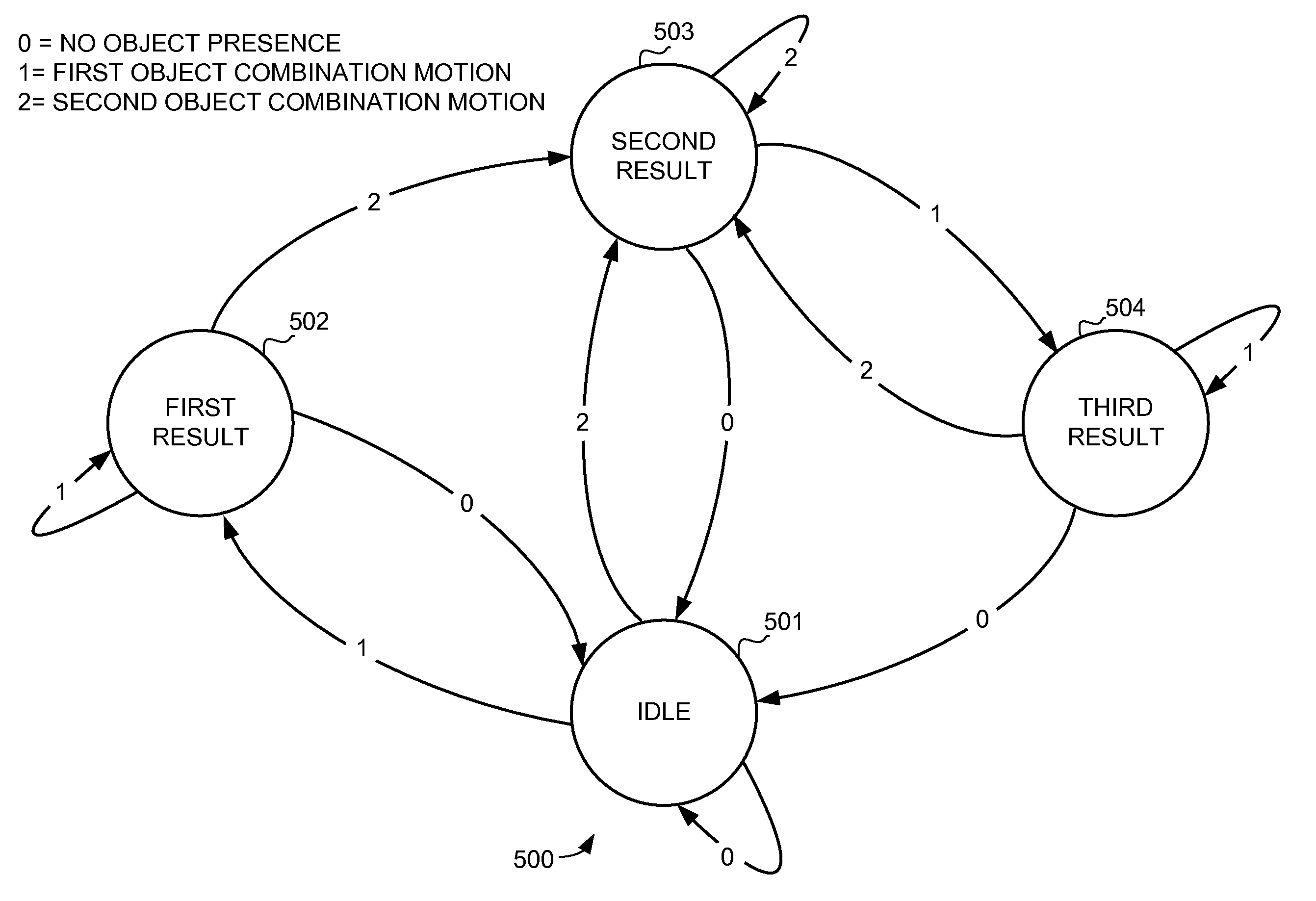
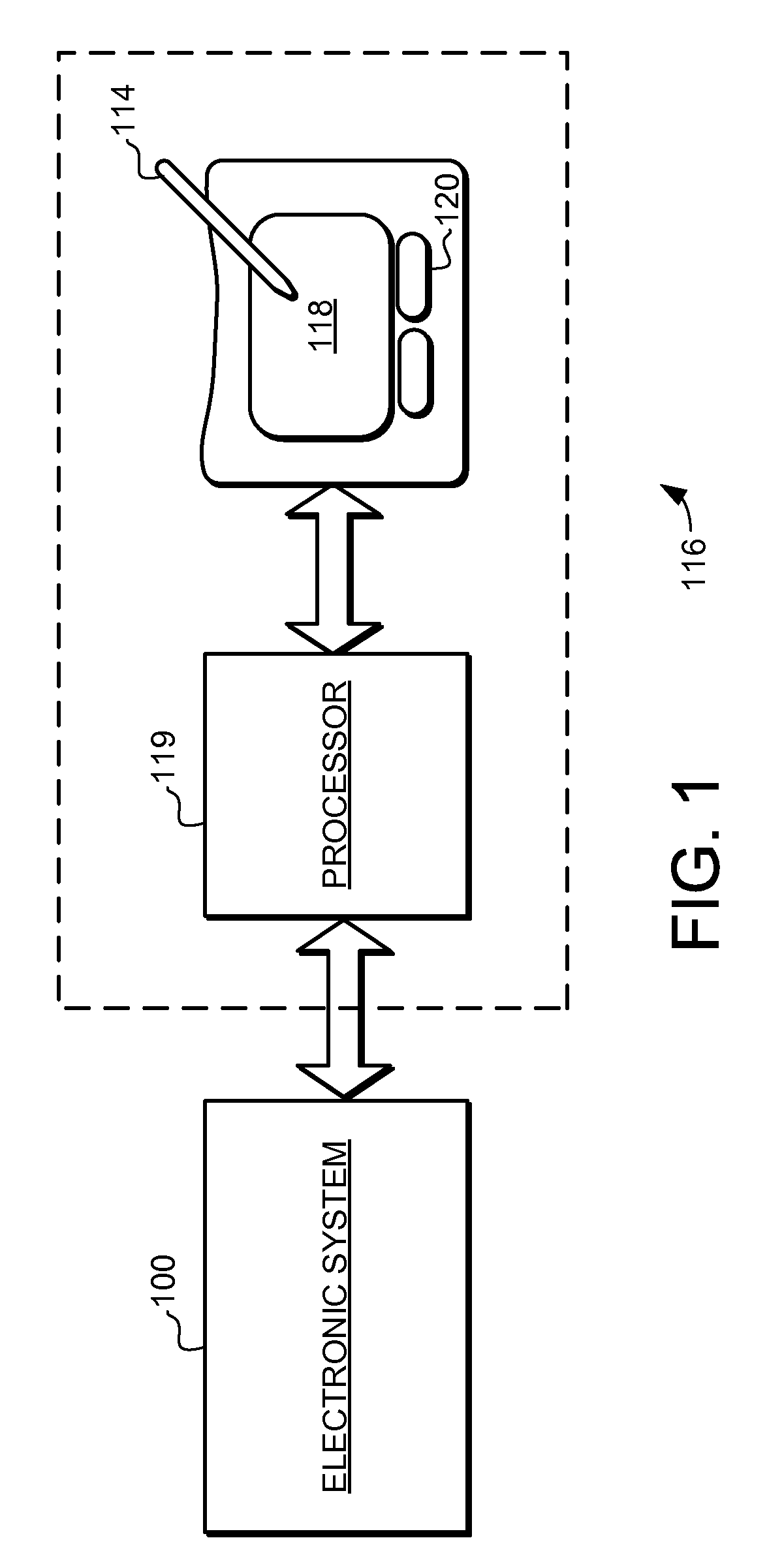
[0020]The present invention provides a proximity sensor device and method that facilitates improved system usability. Specifically, the proximity sensor device and method provide a user with the ability to easily cause different results in an electronic system using a proximity sensor device as a user interface. For example, it can be used to facilitate user interface navigation, such as dragging and scrolling.

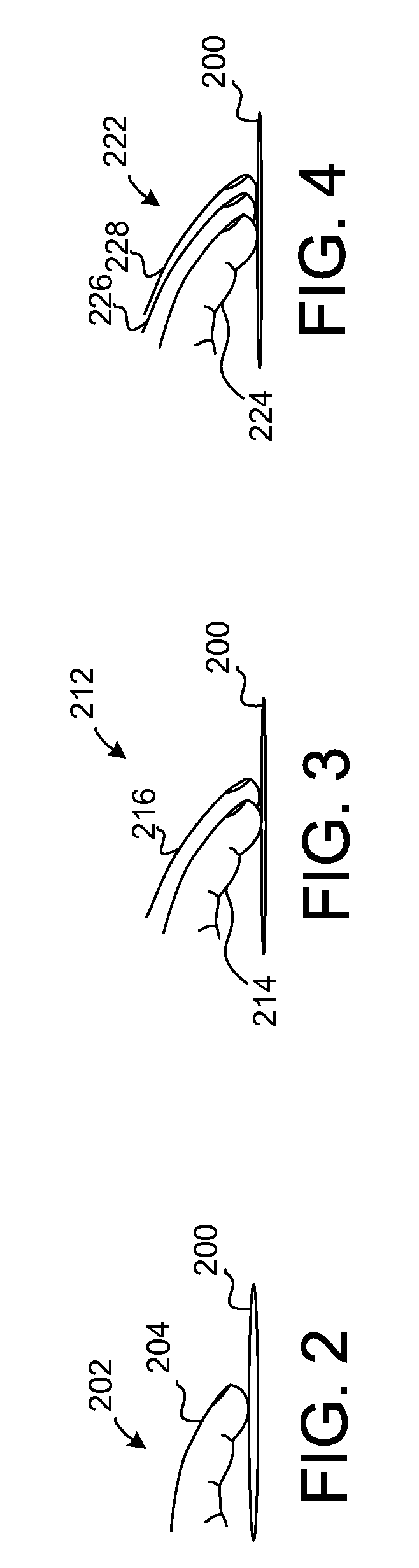
[0021]To cause selective results the proximity sensor device is adapted to distinguish between different object combination motions, determine relative temporal relationships between those motions, and generate user interface results...


PUM


Abstract

A proximity sensor device and method is provided that facilitates improved system usability. Specifically, the proximity sensor device and method provide a user with the ability to easily cause different results in an electronic system using a proximity sensor device as a user interface. For example, it can be used to facilitate user interface navigation, such as dragging and scrolling. As another example, it can be used to facilitate value adjustments, such as changing a device parameter. In general, the proximity sensor device is adapted to distinguish between different object combination motions, determine relative temporal relationships between those motions, and generate user interface results responsive to the motions. This allows a user to selectively generate different results using the motion of two different object combinations.

Description

PRIORITY DATA[0001]This application claims priority of U.S. Provisional Patent Application Ser. No. 60 / 764,406, filed on Feb. 1, 2006, which is hereby incorporated herein by reference.FIELD OF THE INVENTION[0002]This invention generally relates to electronic devices, and more specifically relates to proximity sensor devices and using a touch sensor device for producing user interface inputs.BACKGROUND OF THE INVENTION[0003]Proximity sensor devices (also commonly called touch pads or touch sensor devices) are widely used in a variety of electronic systems. A proximity sensor device typically includes a sensing region, often demarked by a surface, which uses capacitive, resistive, inductive, optical, acoustic and / or other technology to determine the presence, location and / or motion of one or more fingers, styli, and / or other objects. The proximity sensor device, together with finger(s) and / or other object(s), can be used to provide an input to the electronic system. For example, proxi...

Claims


Application Information

Patent Timeline
Patent Type & Authority Applications(United States)
IPC IPC(8): G06F3/041
CPCG06F2203/04808G06F3/04883
Inventor WARREN, ANDREW I.
Owner WACOM CO LTD
Why Eureka
Try Eureka