Rests

a technology for rests and bolsters, applied in the field of rests, can solve problems such as the limitation of the range of shots, and achieve the effect of increasing the degree of confiden

Inactive Publication Date: 2007-08-02
GRAINGER STEPHEN
View PDF13 Cites 8 Cited by
  • Summary
  • Abstract
  • Description
  • Claims
  • Application Information

AI Technical Summary

Benefits of technology

[0008]The design of the head is thus such as to enable the player to strike the ball using his normal cueing action rather than having to lift the butt of the shaft in front of his face. A full range of shots can thus be played with an increased degree of confidence.

Problems solved by technology

The cueing action that a player adopts is thus not the same as that which he normally adopts and there are limitations on the range of shots that he can play using a rest.

Method used


Image

  • Rests
  • Rests
  • Rests

Examples


Embodiment Construction

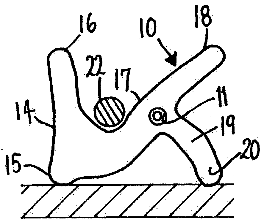
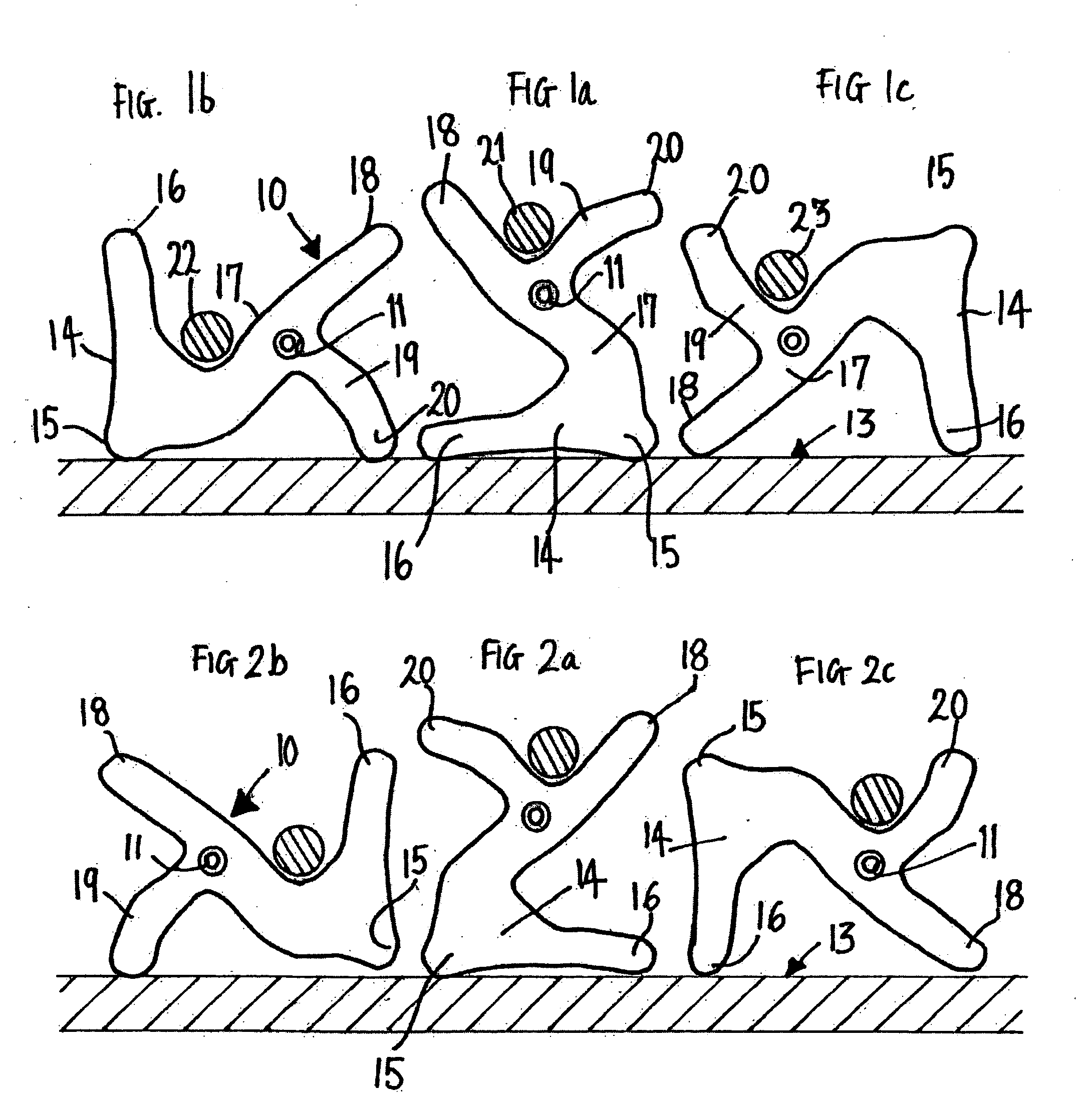
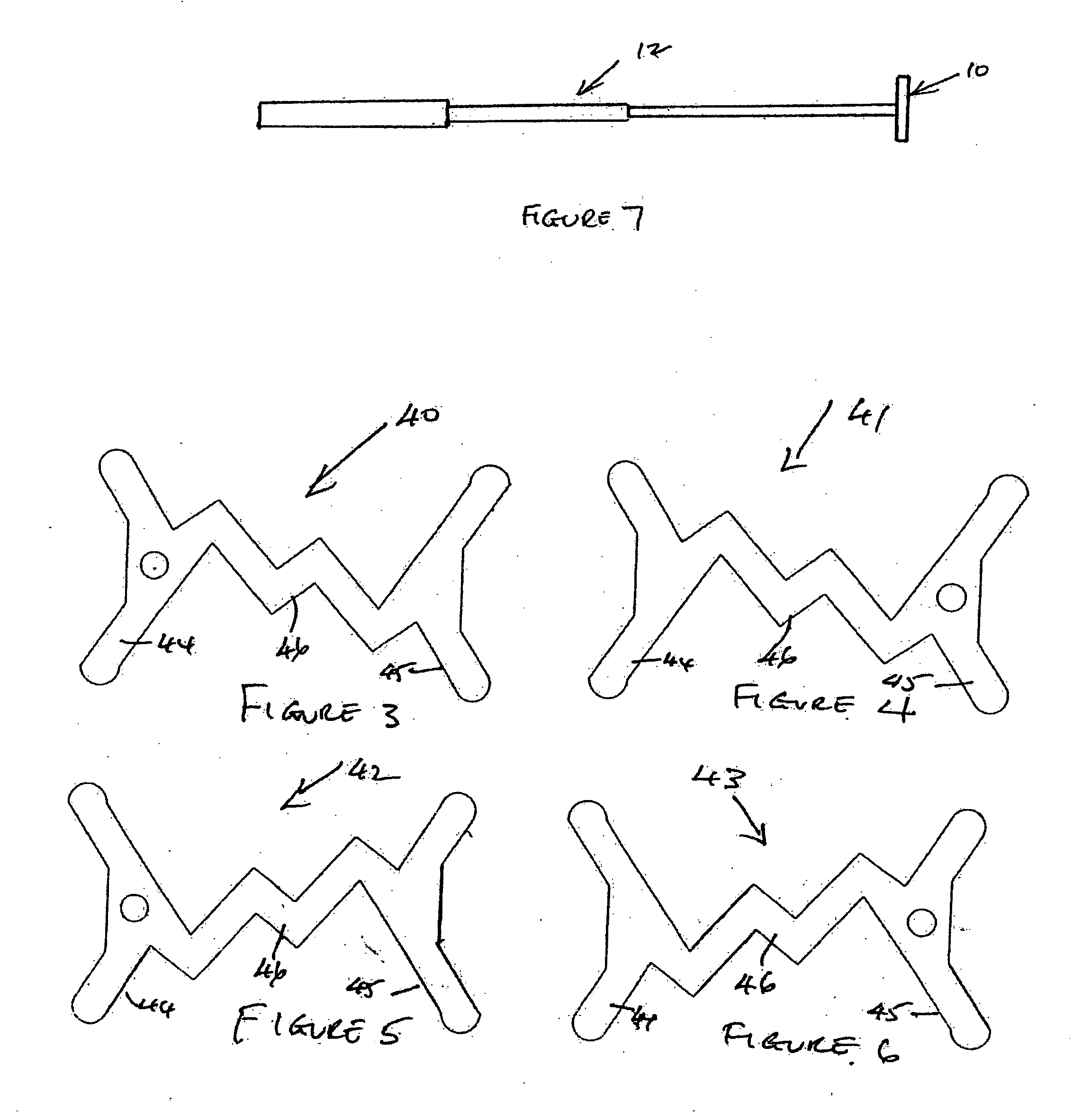
[0014]The head 10 shown in FIGS. 1, 2 and 7 includes an internally threaded socket 11 that is open at both ends and receives the end of a shaft 12. The shaft 12 will normally be telescopically adjustable, for example, within the range of from 600 mm. to 1,000 mm. in length. The shaft 12 may alternatively be of fixed length, for example, 600 mm. in length or 1,500 mm. in length. The shaft 12 may also have means for attachment of a cue extension. The end of the shaft 12 has releasable threaded engagement in the socket 11 of the head 10, so as to permit reversal of the head 10 relative to the shaft 12 to permit use of the rest by a left-handed player as well as by a right-handed player.

[0015]As an alternative to having a threaded connection between the end of the shaft 12 and the head 10, a plug-in connection may be provided between the end of the shaft 12 and the head 10.

[0016]FIG. 1 shows three positions of the head 10 relative to the support surface 13, i.e. the table, on which it i...


PUM


Abstract

A rest for use in playing snooker, billiards and similar games comprises a shaft (12) and a head (10). The head (10) includes a fitting (11) for connection to the shaft (12) and has a configuration such that it can provide support for a cue at a number of different spacings from a support surface on which the rest is placed.

Description

FIELD OF THE INVENTION[0001]This invention relates to rests and is concerned with the provision of an improved form of rest for use when playing snooker, billiards and other similar games, such games being referred to hereinafter for convenience as snooker.[0002]A typical form of snooker rest comprises a shaft and a head that is of X-form so that two limbs of the X are placed on the snooker table and the cue that is being used to make a shot passes between the other two limbs of the X. Another known form of rest is a butt rest that comprises a pair of spaced vertical limbs that are interconnected by a curved bridge or support surface on which the cue is supported.[0003]The design of the standard form of rest used when playing snooker is such that, when a player makes a shot using the rest, the butt of the cue that the player is holding is positioned in front of the player's face, rather than the player holding the cue with his normal playing stance.[0004]The cueing action that a pla...

Claims


Application Information

Patent Timeline
Patent Type & Authority Applications(United States)
IPC IPC(8): A63D15/10
CPCA63D15/105
Inventor GRAINGER, STEPHEN
Owner GRAINGER STEPHEN
Why Eureka
Try Eureka