
Traction control method for a tracked vehicle

a technology of traction control and tracked vehicles, applied in vehicle position/course/altitude control, braking systems, instruments, etc., can solve problems such as vehicle sliding and control loss

Active Publication Date: 2007-08-02
ALLISON TRANSMISSION INC
View PDF25 Cites 9 Cited by
  • Summary
  • Abstract
  • Description
  • Claims
  • Application Information

AI Technical Summary

Benefits of technology

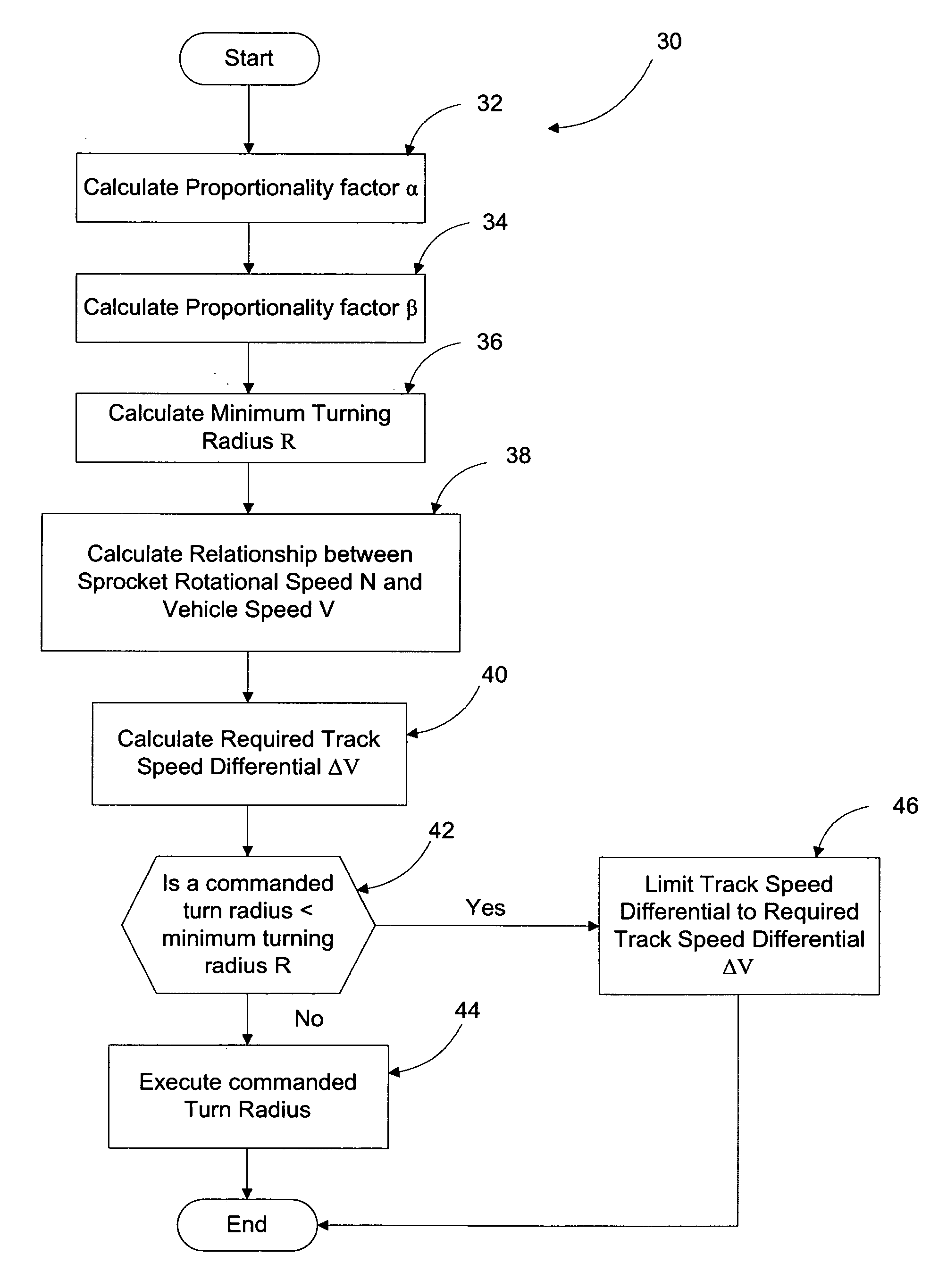
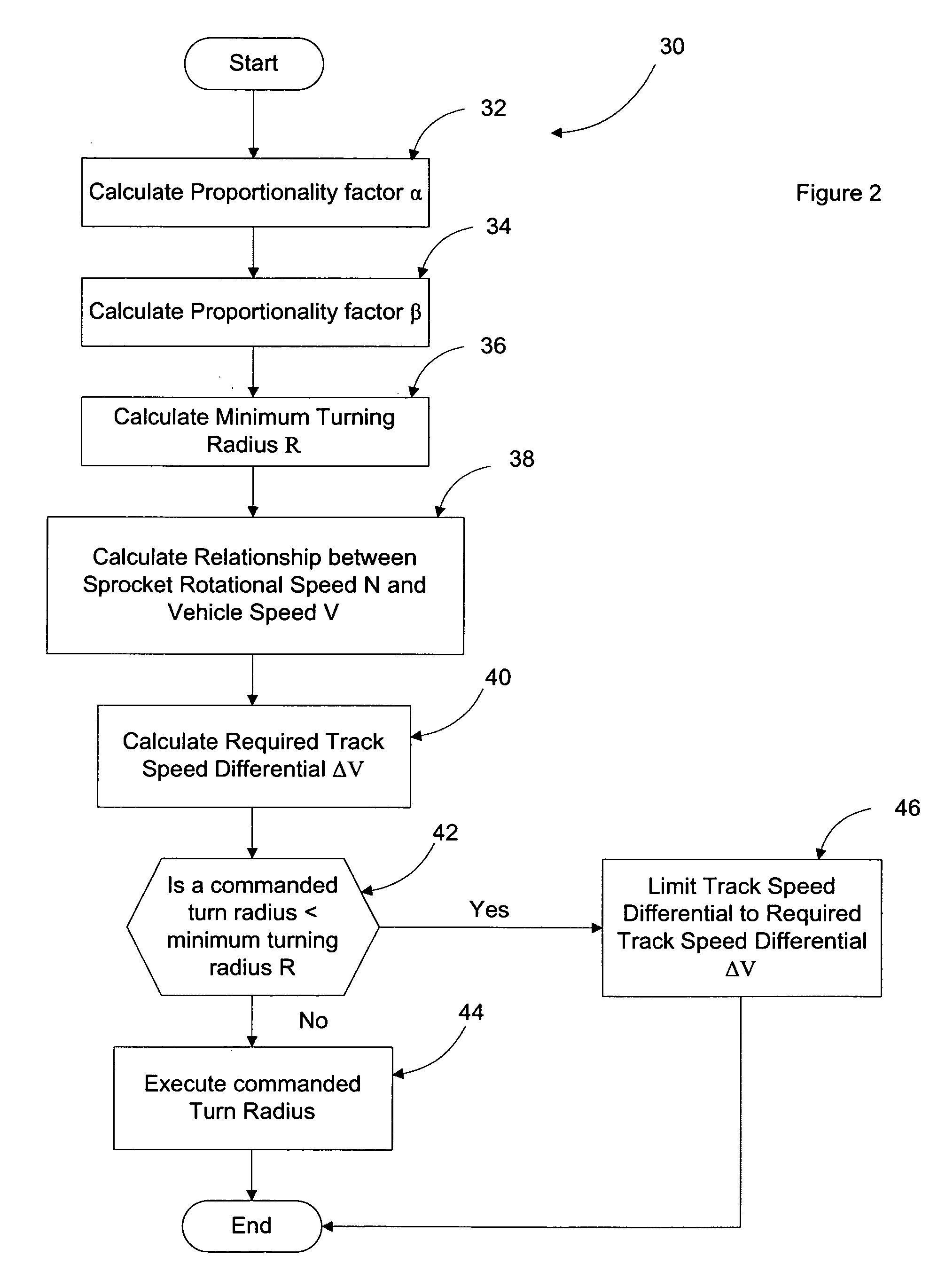
[0003] The present invention provides a traction control method for a tracked vehicle. More precisely, the present invention provides a method for establishing a minimum allowable turn radius calculated to prevent the vehicle from exceeding the 0.7 coefficient of friction. In other words, if the operator commands a turn radius less than the calculated minimum allowable turn radius, the method of the present invention would supersede the operator command and turn the vehicle at the calculated minimum allowable turn radius such that the vehicle does not slip.
[0005] After calculating the required track speed differential configured to turn the tracked vehicle at the minimum turn radius, the method of the present invention determines if a commanded turn radius is less than the minimum turn radius. If the commanded turn radius is greater than or equal to the minimum turn radius, the method of the present invention executes the turn command. If the commanded turn radius is less than the minimum turn radius, the method of the present invention limits the track speed differential of the tracked vehicle to the required track speed differential such that the tracked vehicle does not slip.

Problems solved by technology

If the driver intentionally or accidentally turns too sharply for the current vehicle speed such that the 0.7 coefficient of friction is exceeded, the vehicle will slide and may loose control.

Method used


Image

  • Traction control method for a tracked vehicle
  • Traction control method for a tracked vehicle
  • Traction control method for a tracked vehicle

Examples


Embodiment Construction

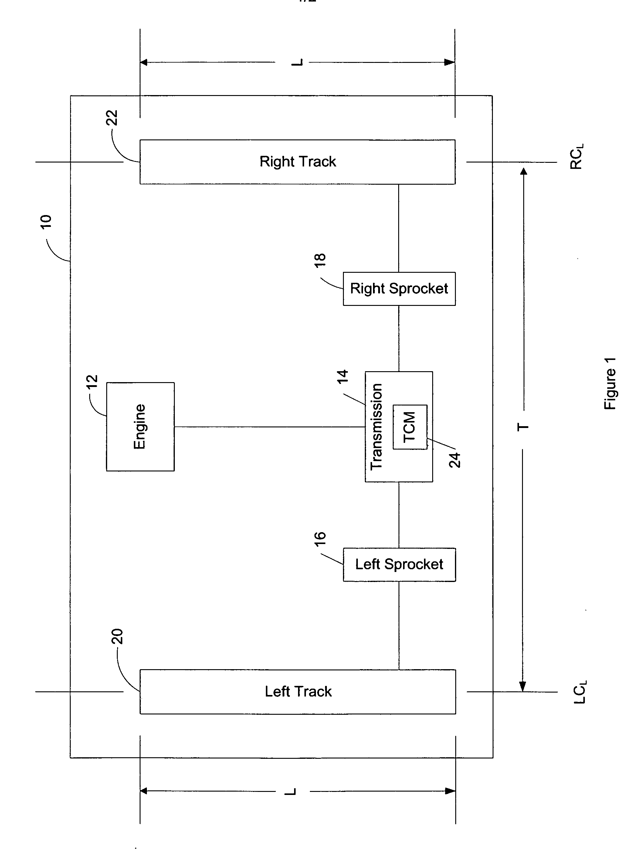
[0009] Referring to the drawings, wherein like reference numbers refer to like components, FIG. 1 shows a schematic depiction of a tracked vehicle 10 having an engine 12, a transmission 14, left sprocket 16, a right sprocket 18, a left track 20, and a right track 22. For purposes of the present invention, tracked vehicles are defined as vehicles that ride on tracks instead of or in addition to wheels, such as, for example, military tanks. The left and right tracks 20, 22 each define a vehicle track length L representing the length of the tracks 20, 22 that is in contact with the ground. The left and right tracks 20, 22 each define a centerline LCL and RCL, respectively. The distance between the left and right track centerlines LCL and RCL is hereinafter referred to as the vehicle track center distance T.

[0010] The tracked vehicle 10 steers by way of a track speed differential □V. The track speed differential □V is defined for purposes of the present invention as difference between ...


PUM


Abstract

The present invention provides a traction control method for a tracked vehicle such as a military tank. The method includes calculating a track proportionality factor and a vehicle proportionality factor based on predefined attributes of the tracked vehicle. A minimum turn radius of the tracked vehicle is calculated based on the velocity of the tracked vehicle, the maximum coefficient of friction between the tracks of the tracked vehicle and the ground (0.7), and gravitational acceleration (9.80665 m / s2). A sprocket rotational speed is calculated based on the pitch diameter of the tracked vehicle sprockets and the velocity of the tracked vehicle. Based on the preceding calculations, the method of the present invention calculates a required track speed differential configured to turn the tracked vehicle at the minimum turn radius. If a commanded turn radius is less than the minimum turn radius, the track speed differential of the tracked vehicle is limited to the required track speed differential to prevent the tracked vehicle from slipping.

Description

TECHNICAL FIELD [0001] The present invention is drawn to a traction control method for a tracked vehicle. BACKGROUND OF THE INVENTION [0002] For purposes of the present invention, tracked vehicles are defined as vehicles that ride on tracks instead of or in addition to wheels, such as, for example, military tanks. A tracked vehicle steers by way of differential track speed which is generally imparted by the transmission. It has been observed that the maximum coefficient of friction (COF or μ) that can be achieved between the tracks and the ground is generally approximately 0.7. If the driver intentionally or accidentally turns too sharply for the current vehicle speed such that the 0.7 coefficient of friction is exceeded, the vehicle will slide and may loose control. The coefficient of friction will hereinafter be defined as a value indicating the amount of friction between two surfaces, wherein a 0.0 COF represents no friction and a 1.0 COF represents the maximum friction. SUMMARY ...

Claims


Application Information

Patent Timeline
Patent Type & Authority Applications(United States)
IPC IPC(8): B60T7/12
CPCB62D11/003B60T11/21
Inventor OEHME, CLIFFORD H.
Owner ALLISON TRANSMISSION INC
Learn More