Beach cabana

a beach cabana and hammock technology, applied in the field of beach cabanas, can solve problems such as difficult to achiev

Inactive Publication Date: 2007-08-09
SUNDIAL CABANA
View PDF0 Cites 25 Cited by
  • Summary
  • Abstract
  • Description
  • Claims
  • Application Information

AI Technical Summary

Benefits of technology

[0004]In one embodiment the present invention there is provided a novel configuration for a portable beach cabana. The cabana provides for two users to have individual lounge chair type portions. Further the configuration of the present invention has a passageway between the individual lounge chair portions and provides the ability of a person to walk in the area between the two lounge chairs.

Problems solved by technology

Additionally current beach cabanas are large, cumbersome, and heavy when a user wants to change the orientation of the cabana for example relative to the position of the sun, it may prove to be very difficult.

Method used


Image

  • Beach cabana
  • Beach cabana
  • Beach cabana

Examples


Embodiment Construction

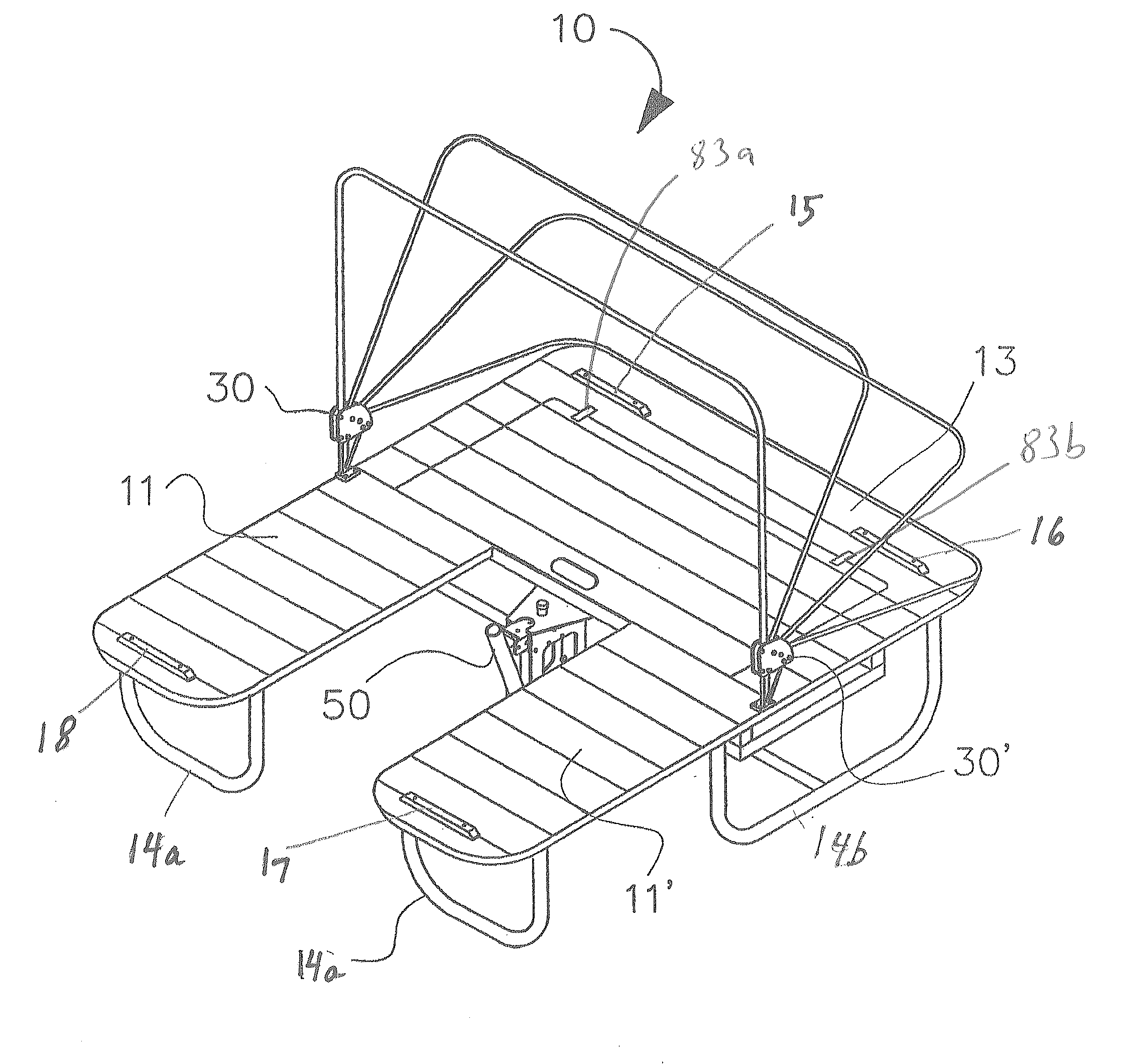
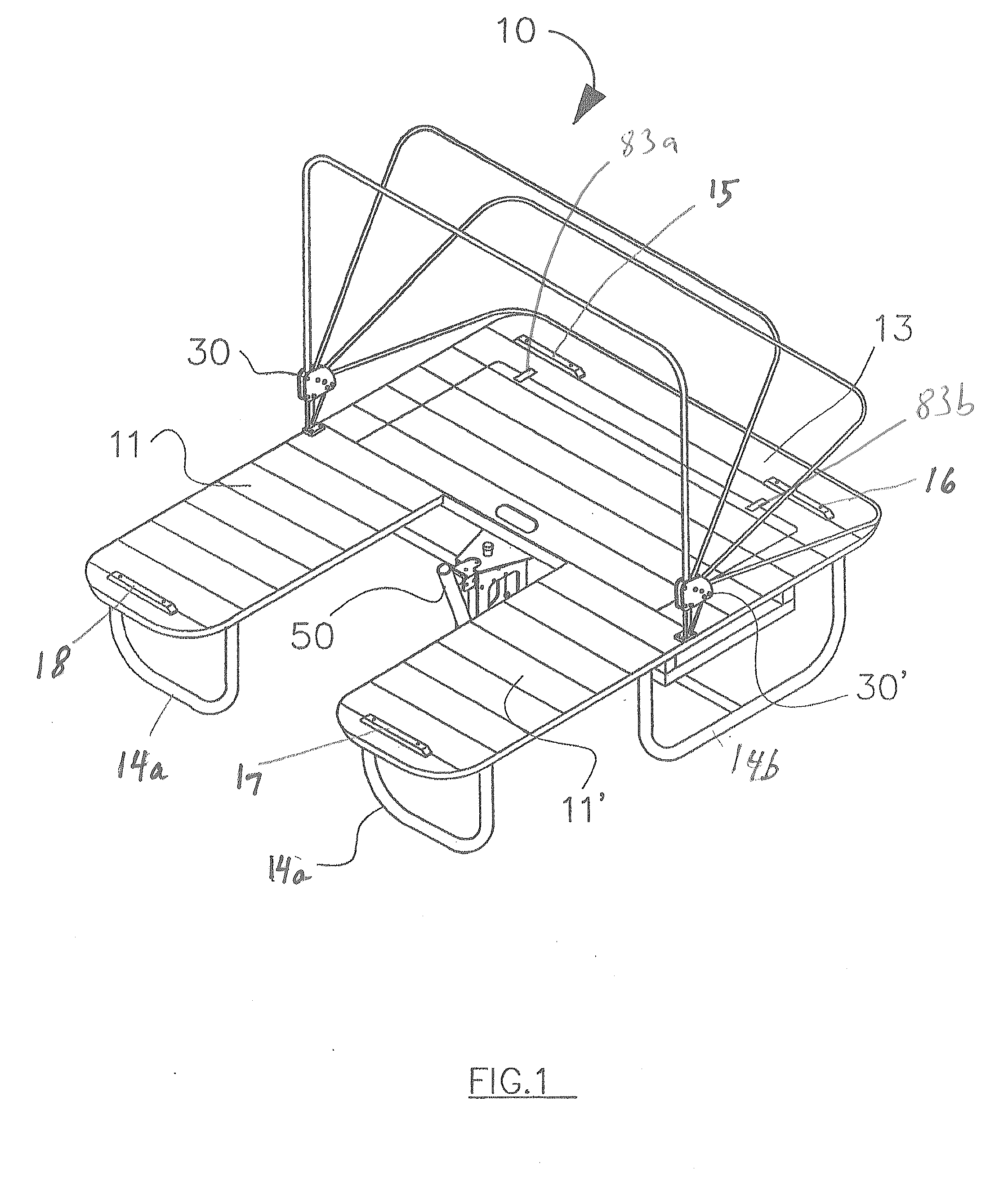
[0053]The beach cabana 10 of the present invention provides for a single frame assembly. The frame may be made of any acceptable material such as metal, metal alloys, plastic, or other synthetic material such that the frame supports the desired weight. Acceptable material must be such that it can support the weight of lounge chairs and at least 2 adults. Preferably, the frame should be able to support 600 to 700 pounds.

[0054]In FIG. 1 cabana 10 is shown in one embodiment. Two lounge portions 11 and 11′ extend outward from a platform area 13 such that the overall configuration is of a simplified squared letter “u.” The area between each of lounge portions 11 and 11′ forms a passage that allows a user to walk or move within the area or at least come within the cabana area in the center passage.

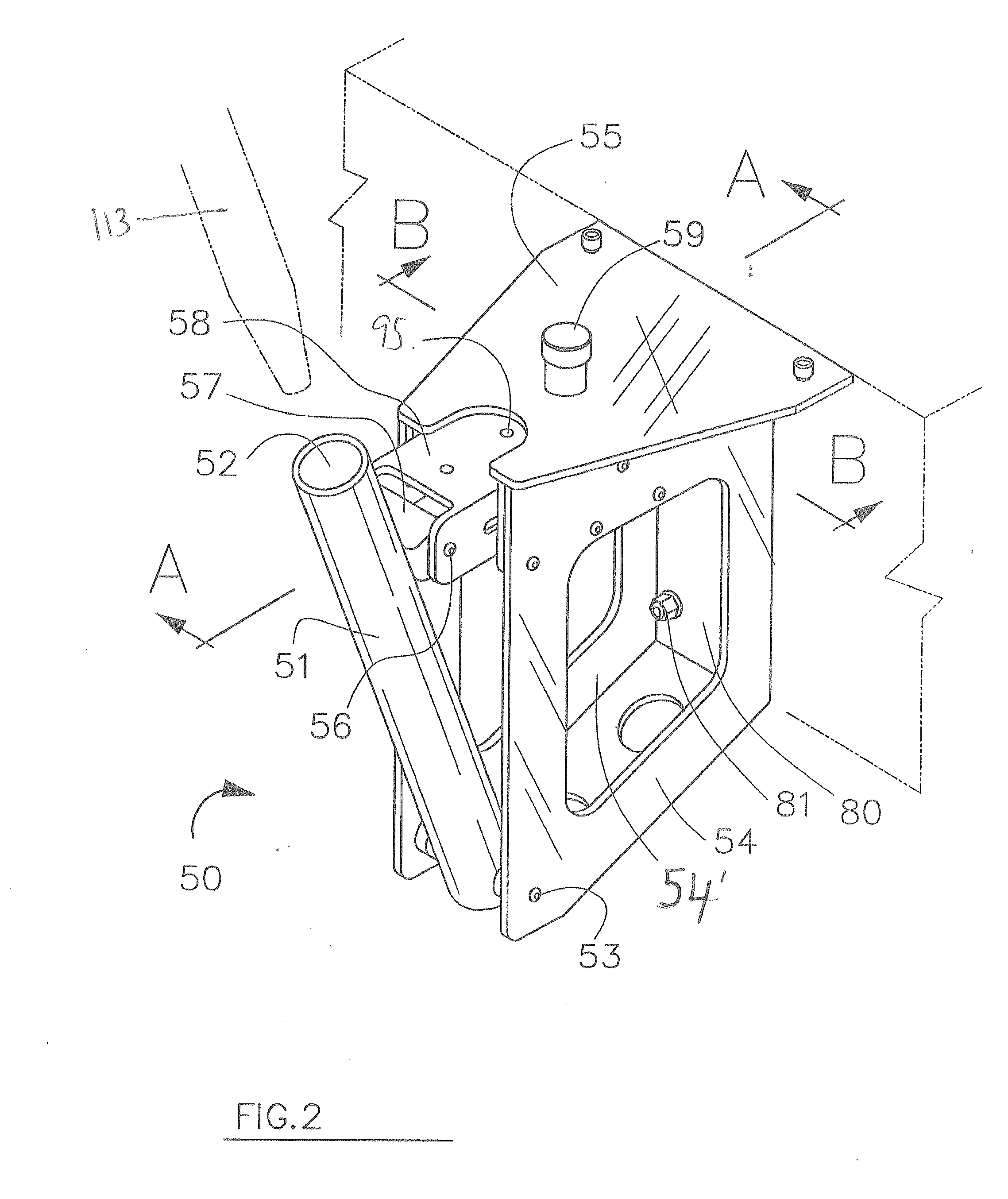
[0055]Unitary frame 12 includes a configuration of tubular parallel and perpendicular cross members, FIG. 12A, arranged to support lounge portions 11 and 11′, and platform area 13. Portions 11, ...


PUM


Abstract

The present invention is a beach cabana that provides a central corridor between two lounge portions and a frame rotatable about an axis.

Description

INDEX TO RELATED APPLICATIONS[0001]This application claims benefit to U.S. Patent application Ser. No. 60 / 765,977 filed Feb. 7, 2006; U.S. Patent application Ser. No. 60 / 746,793 filed May 9, 2006 and U.S. Patent Application Ser. No. 60 / 844,740 filed Sep. 15, 2006 the disclosures of which are all incorporated herein by reference in their entirety.BACKGROUND OF THE INVENTION[0002]The recreation industry is replete with articles intended to improve the comfort and convenience of sunbathers, pool patrons, and beachgoers. The simple beach lounge has evolved into the central component of portable beach cabanas. Typically, beach cabanas are single and double units. A double unit usually includes a broad area for two persons to lounge side by side with an umbrella or canopy blocking the sun. While these cabanas have provided greater service and convenience to their users they still have shortcomings. One particular shortcoming is that a user is required to enter and leave the beach lounge p...

Claims


Application Information

Patent Timeline
Patent Type & Authority Applications(United States)
IPC IPC(8): E04H15/36E04H15/02
CPCA47C1/14E04H15/38E04H15/003
Inventor HARRISON, JAMES
Owner SUNDIAL CABANA
Why Eureka
Try Eureka