In-line jet pumps and methods of use

a jet pump and jet technology, applied in the field of jet pumps, can solve the problems of heavy equipment, difficult maneuverability, and large equipment for removing

Inactive Publication Date: 2008-02-21
WALKER DAWSON INTERESTS
View PDF9 Cites 8 Cited by
  • Summary
  • Abstract
  • Description
  • Claims
  • Application Information

AI Technical Summary

Benefits of technology

[0003]The present inventions meet this need, amongst others by providing an in-line jet pump for suctioning material, which can be attached to an arm of a piece of equipment such as a backhoe and which can be manipulated so that the suction inlet is in very close proximity to the material to be suctioned. The novel configuration of the in-line jet pump of this invention enables close-in work in such locations as, for example, marinas, boat slips and small sediment ponds.

Problems solved by technology

When materials such as silts, sand and / or mud located at the bottoms of water bodies need to be removed, the equipment for accomplishing the removal is typically massive, heavy and difficult to maneuver.

Method used


Image

  • In-line jet pumps and methods of use
  • In-line jet pumps and methods of use
  • In-line jet pumps and methods of use

Examples


example 1

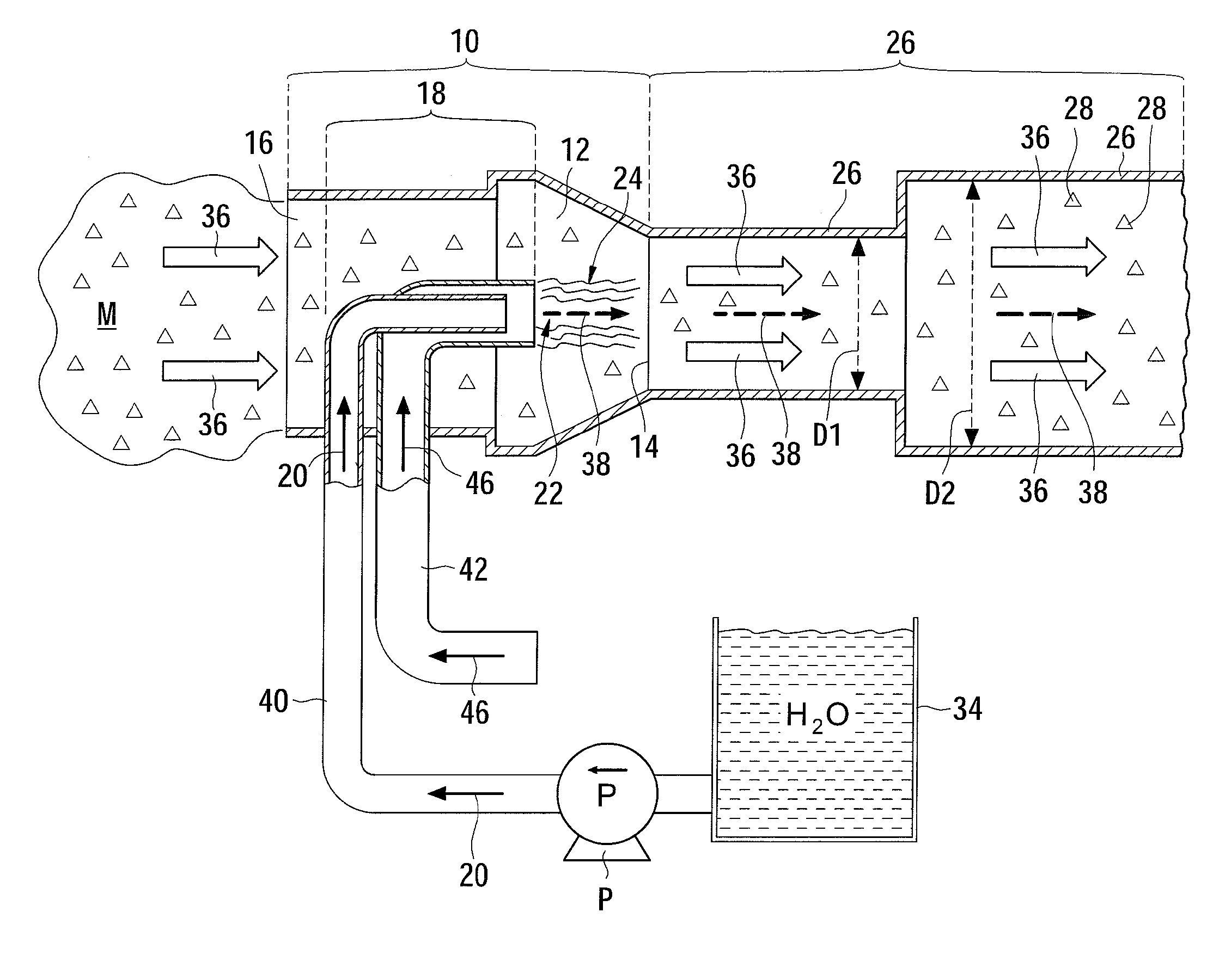
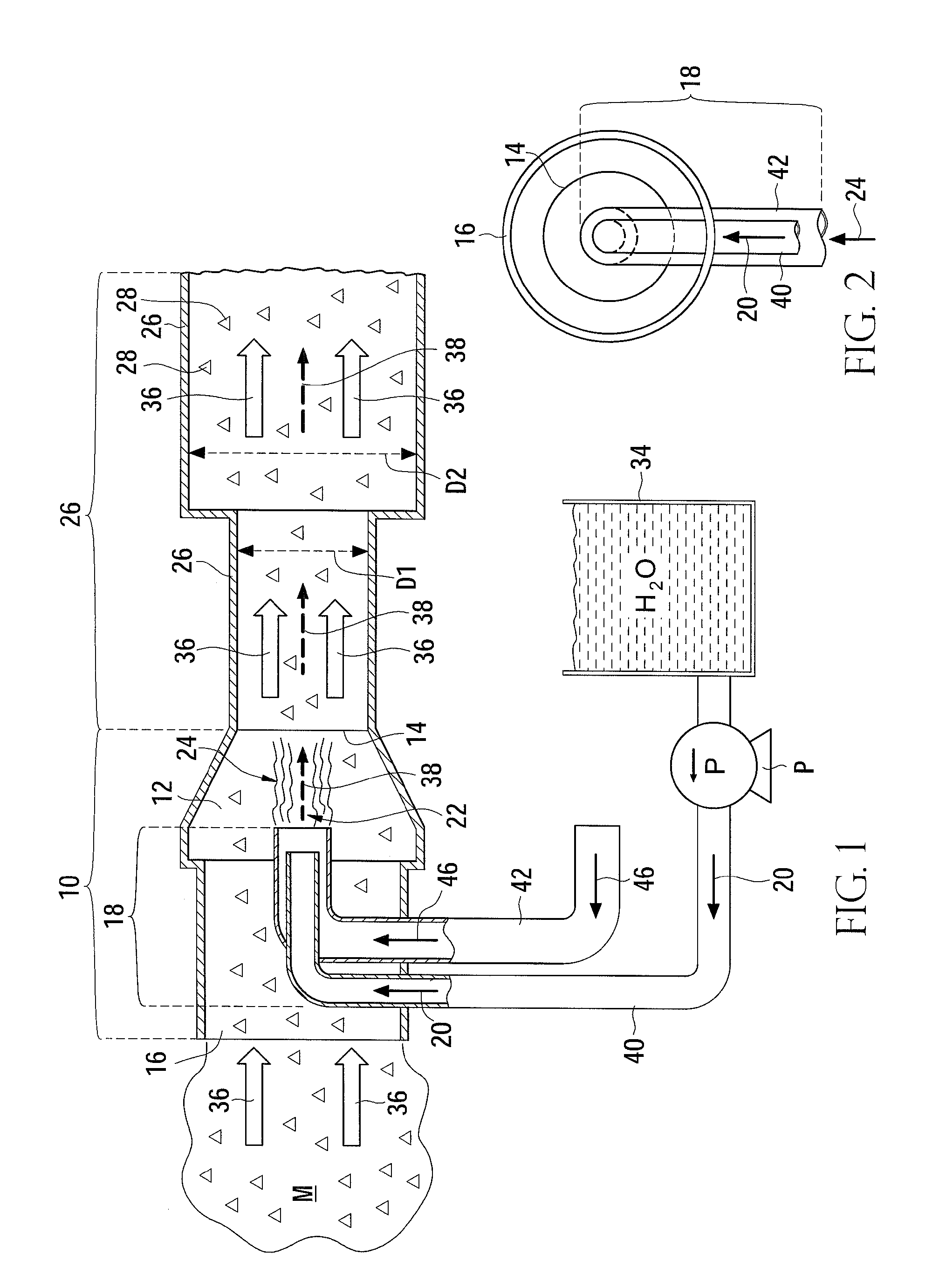
[0039]The inline jet pump was demonstrated to have superior material-moving capabilities of a rate of movement of a slurry of sand, silt and water of at least about 50 tons (4.5×10⁴ kg) per hour when the second inner diameter of the discharge conduit was about 4 inches (10.2 cm), the first inner diameter of the discharge conduit was about 3 inches (7.6 cm), the diameter of the nozzle assembly at the point of ejection of the pressurized fluid was about 0.625 inches (1.59 cm), pressurized fluid pressure was about 150 psi (1034 kPa), and the flow rate of the pressurized fluid was about 143 gallons (541 L) per minute.

example 2

[0040]Even better performance of the inline jet pump of a rate of movement of a slurry of sand, silt and water of at least about 100 tons (9.1×10⁴) kg) per hour was attained when the second inner diameter of the discharge conduit was about 6 inches (15.24 cm), the first inner diameter of the discharge conduit was about 4 inches (10.2 cm), the diameter of the nozzle assembly at the point of ejection of the pressurized fluid was about 0.875 inch (2.22 cm), the pressurized fluid pressure was about 150 psi (1034 kPa), and the flow rate of the pressurized fluid was about 280 gallons (1060 L) per minute.

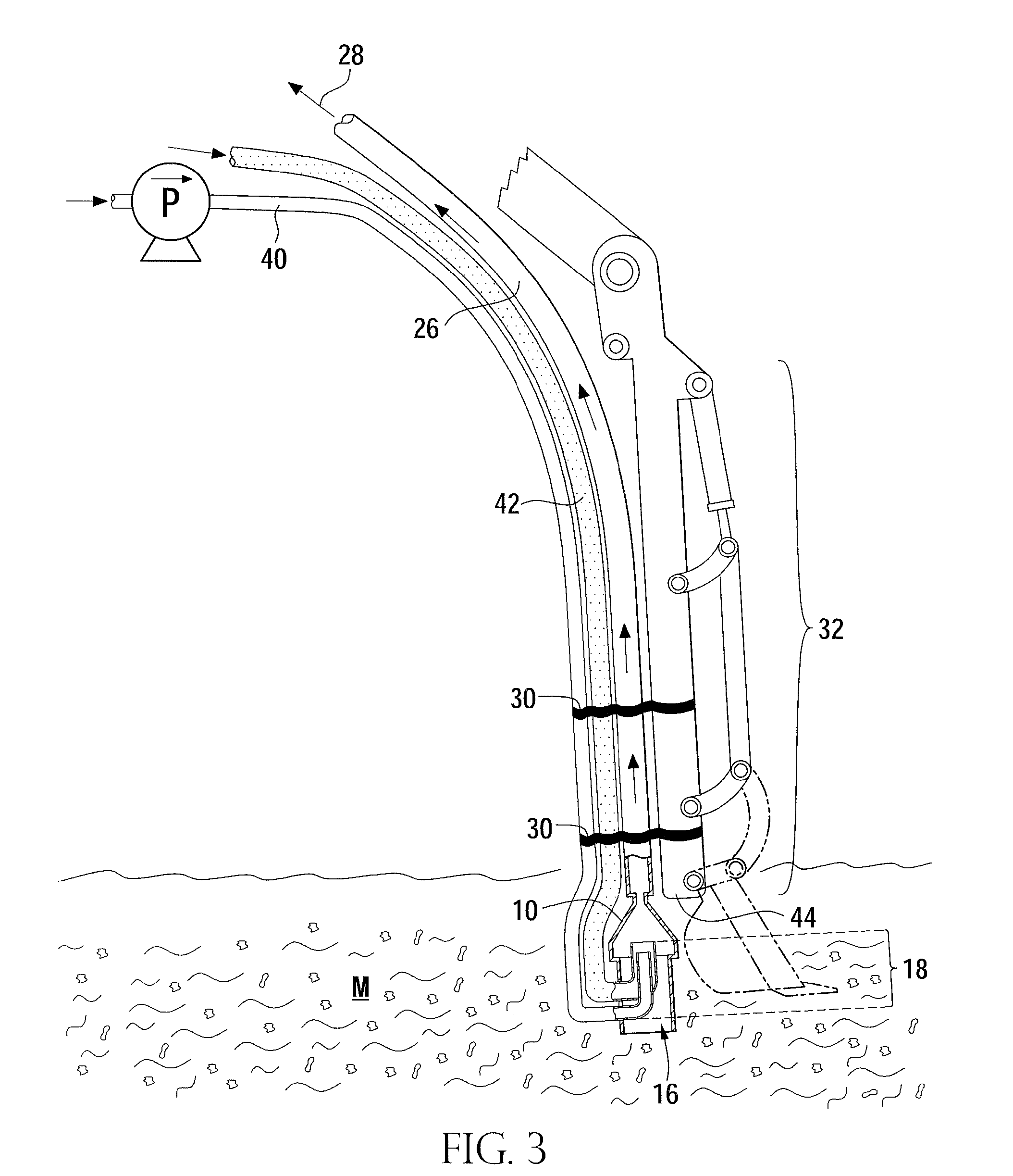
[0041]The present invention can be used in any application requiring significant suction effect on solid material in a liquid or gaseous environment. The dimensions of the various component parts of jet pumps and systems of this invention may vary depending upon the circumstances in which the jet pump or system will be employed, so long as the dimensions permit the components to function a...


PUM


Abstract

A jet pump comprising (A) a housing which defines at least a suction chamber, a suction inlet and a suction outlet; (B) a nozzle assembly disposed within the housing which nozzle assembly is sized and configured to receive at least a pressurized fluid and eject the pressurized fluid as a fluid flow into a portion of the suction chamber; and (C) a discharge conduit extending from the suction outlet away from the suction chamber, the discharge conduit being configured for fluid communication with the suction chamber and being disposed to receive the fluid flow from the nozzle assembly, wherein the discharge conduit defines at least a first inner diameter along a portion of its length and a second inner diameter along another portion of its length, the first inner diameter being less than the second inner diameter. The housing is configured so that the suction inlet provides a flow of suctioned material into the suction chamber which has a predominant direction of flow of suctioned material which is substantially parallel to a predominant direction of flow of the fluid flow from the nozzle assembly when the jet pump is in use.

Description

FIELD OF THE INVENTION[0001]This invention relates generally to hydraulic nonmechanical pumping devices for transferring material, and specifically, to jet pumps for moving solid, semi-solid, slurried and / or liquid materials, as well as related methods.BACKGROUND[0002]When materials such as silts, sand and / or mud located at the bottoms of water bodies need to be removed, the equipment for accomplishing the removal is typically massive, heavy and difficult to maneuver. Therefore, a need exists for an apparatus of relatively small dimensions and lighter weight which can be manipulated in areas which present logistical problems for larger equipment such as drag lines, large excavators, and the like.SUMMARY OF THE INVENTION[0003]The present inventions meet this need, amongst others by providing an in-line jet pump for suctioning material, which can be attached to an arm of a piece of equipment such as a backhoe and which can be manipulated so that the suction inlet is in very close prox...

Claims


Application Information

Patent Timeline
Patent Type & Authority Applications(United States)
IPC IPC(8): F04F5/00
CPCE02F3/8825E02F3/9243F04F5/54F04F5/10F04F5/463F04F5/02
Inventor DAWSON, RICHARD F.DAWSON, RICHARD R.
Owner WALKER DAWSON INTERESTS
Why Eureka
Try Eureka