Heat transfer fin and fin-tube heat exchanger

a heat exchanger and heat transfer fin technology, which is applied in the direction of tubular elements, lighting and heating apparatus, stationary conduit assemblies, etc., can solve the problems of increasing the pressure loss of the fluid that passes through the heat exchanger, and achieves improved heat transfer coefficient of the heat transfer fin, high performance, and prevent the effect of increasing pressure loss

Inactive Publication Date: 2013-08-13
PANASONIC CORP
View PDF24 Cites 9 Cited by
  • Summary
  • Abstract
  • Description
  • Claims
  • Application Information

AI Technical Summary

Benefits of technology

[0006]The present invention has been accomplished in view of the foregoing circumstances, and it is an object of the invention to provide a novel fin and a novel fin-tube heat exchanger that can improve the heat transfer coefficient and at the same time prevent the pressure loss from increasing.
[0029]The present invention makes it possible to improve the heat transfer coefficient of the heat transfer fin and at the same time prevent the pressure loss from increasing. In addition, the present invention makes available a high performance fin-tube heat exchanger that has a novel configuration.

Problems solved by technology

However, as the velocity of the fluid flowing over the fin surface becomes higher, the pressure loss of the fluid that passes through the heat exchanger correspondingly increases.

Method used


Image

  • Heat transfer fin and fin-tube heat exchanger
  • Heat transfer fin and fin-tube heat exchanger
  • Heat transfer fin and fin-tube heat exchanger

Examples


Embodiment Construction

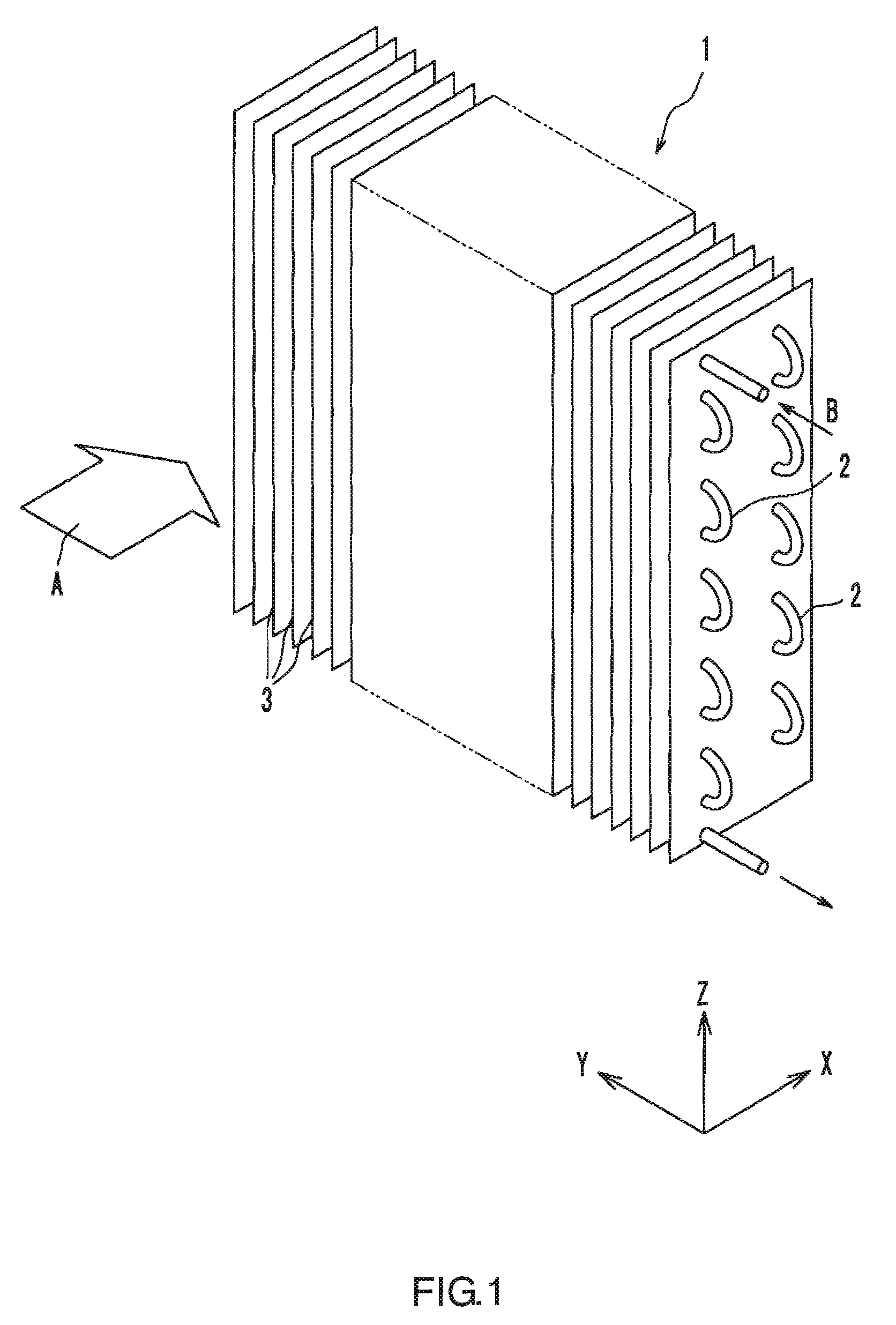
[0040]Hereinbelow, embodiments of the present invention are described in detail with reference to the drawings.

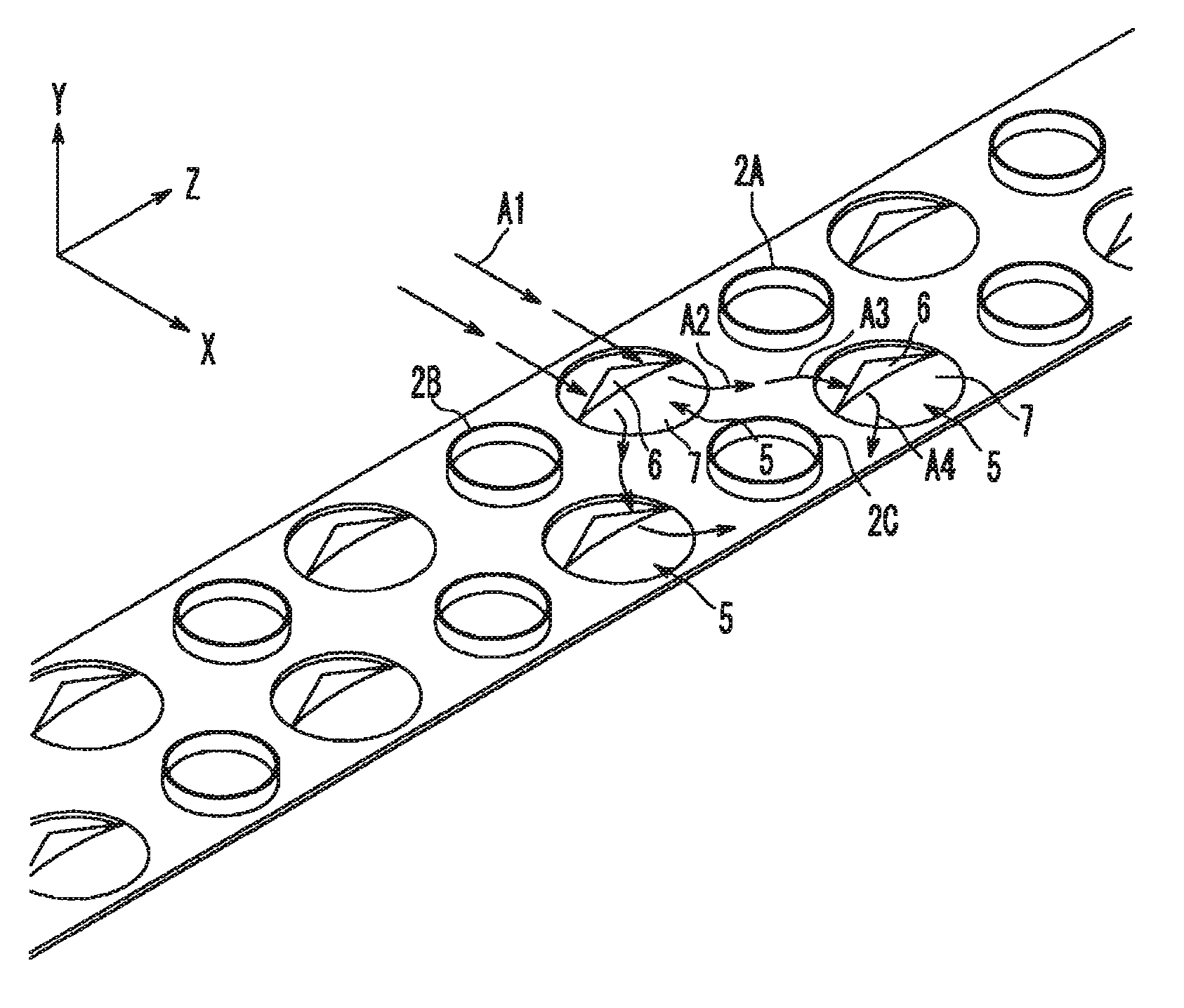
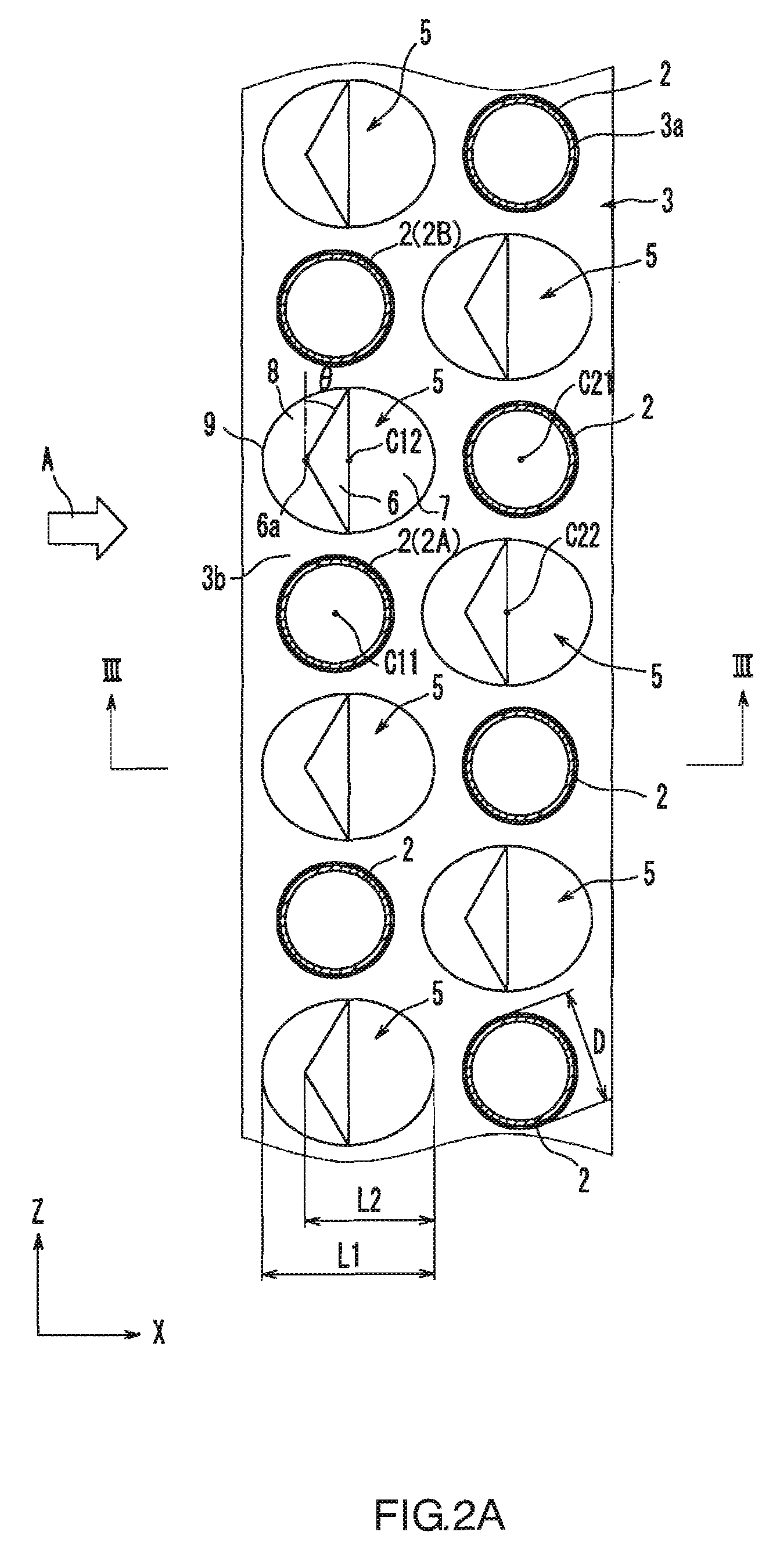
[0041]As illustrated in FIG. 1, a fin-tube heat exchanger 1 according to an embodiment has a plurality of fins 3 arranged at a predetermined spacing and parallel to each other so as to form spaces for allowing air A to pass therethrough, and a plurality of heat transfer tubes 2 penetrating these fins 3. The heat exchanger 1 is for exchanging heat between the fluid flowing inside the heat transfer tubes 2 and the fluid flowing along the surfaces of the fins 3. In the present embodiment, the air A flows along the surfaces of the fins 3, and refrigerant B flows inside the heat transfer tubes 2. It should be noted that the type and state of the fluid that flows inside the heat transfer tubes 2 and those of the fluid that flows along principal surfaces of the fins 3 are not particularly limited. Each of the fluids may be either a gas or a liquid. The plurality of heat transfer t...


PUM


Abstract

A fin (3) of a fin-tube heat exchanger (1) has protuberances (5) each disposed between two adjacent heat transfer tubes (2, 2) and holes 8 (cut-outs) each formed upstream of the protuberances (5). Each of the protuberances (5) has, as an upstream portion adjacent to the hole (8), a wing portion (6) tapering toward an upstream side.

Description

TECHNICAL FIELD[0001]The present invention relates to heat transfer fins and fin-tube heat exchangers.BACKGROUND ART[0002]Conventionally, various types of heat transfer fins have been used for, for example, home or automobile air conditioners, freezer-refrigerators, dehumidifiers, and water heaters. Fin-tube heat exchangers, in which heat transfer fins and heat transfer tubes are combined, also are commonly used. A fin-tube heat exchanger is constructed of a plurality of heat transfer fins arranged at a predetermined fin pitch, and heat transfer tubes penetrating these fins.[0003]In this type of heat exchanger, the heat transfer coefficient of the fin increases when the velocity of the fluid flowing over the fin surface is increased. However, as the velocity of the fluid flowing over the fin surface becomes higher, the pressure loss of the fluid that passes through the heat exchanger correspondingly increases. Thus, there is a trade-off between the pressure loss and the heat transfe...

Claims


Application Information

Patent Timeline
Patent Type & Authority Patents(United States)
IPC IPC(8): F28D1/04F28F1/20F28F1/30F28F1/14
CPCF28D1/0477F28F1/325
Inventor OGAWA, OSAMUKOMORI, KOUHAYASHI, HIROKI
Owner PANASONIC CORP
Why Eureka
Try Eureka