Variable flow valve mechanism and vehicle turbocharger

a technology of variable flow valve and vehicle, which is applied in the direction of combustion engines, machines/engines, output power, etc., can solve the problems of difficult to secure a high level of quietness in a vehicle in motion, chattering noise, so as to reduce the vibration of the valve, eliminate or minimize the occurrence of chattering noise, and secure a high level of quietness

Active Publication Date: 2014-12-18
IHI CORP
View PDF2 Cites 8 Cited by
  • Summary
  • Abstract
  • Description
  • Claims
  • Application Information

AI Technical Summary

Benefits of technology

[0017]The present invention can sufficiently reduce vibrations of the valve in the state where the opening of the gas passage is opened. Accordingly, it is possible to eliminate occurrence of or minimize chattering noise, and to secure a high level of quietness in a vehicle in motion.
[0018]In addition, even if any of the spacers is partially broken while the vehicle turbocharger is in operation, fragments and the like of the spacer can be prevented from flowing out of the guard wall. Thus, it is possible to sufficiently prevent damage to an exhaust system, such as a catalyst, arranged on the downstream of the vehicle turbocharger (on the downstream in a flowing direction of the exhaust gas).

Problems solved by technology

Nevertheless, once the waste gate valve opens the opening of the bypass passage when the pressure on the outlet side of the compressor wheel reaches the preset pressure, the valve vibrates due to: a pulsation pressure of the exhaust gas from the engine; vibrations of the engine; and the like.
For this reason, the valve and the washer clash with the attachment member and cause so-called chattering noise.
Hence, there is a problem that it is difficult to secure a high level of quietness in a vehicle in motion.
Note that this problem caused by the vibrations of the valve occurs not only in the waste gate valve provided in the turbine housing but also in other variable flow valve mechanisms used in turbochargers.

Method used


Image

  • Variable flow valve mechanism and vehicle turbocharger
  • Variable flow valve mechanism and vehicle turbocharger
  • Variable flow valve mechanism and vehicle turbocharger

Examples


Embodiment Construction

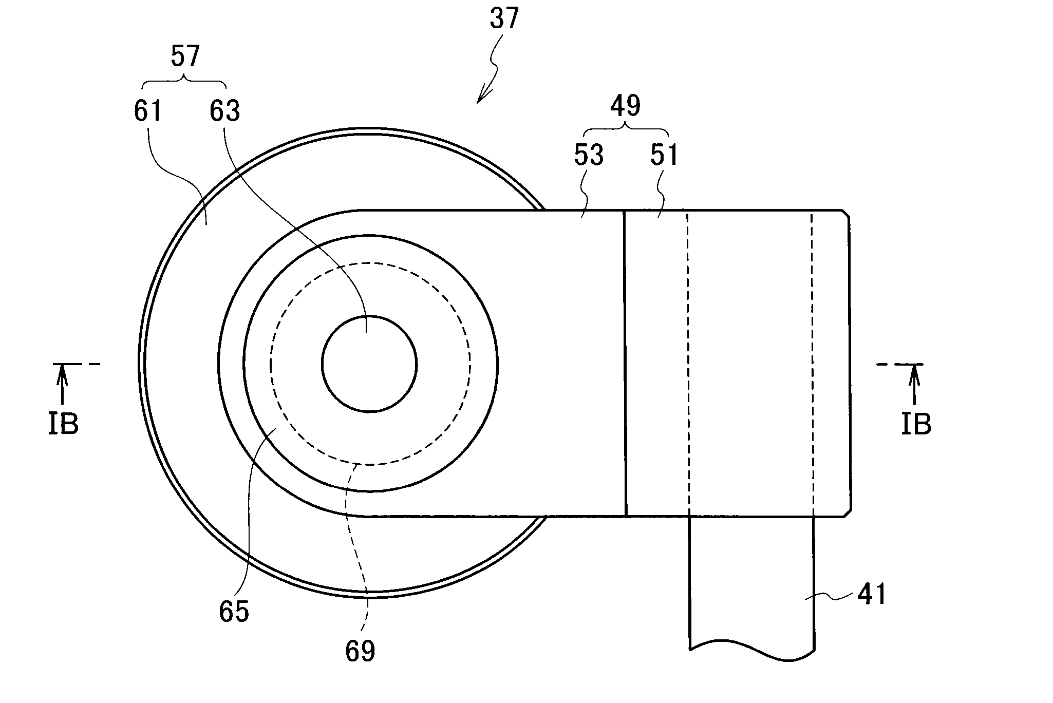
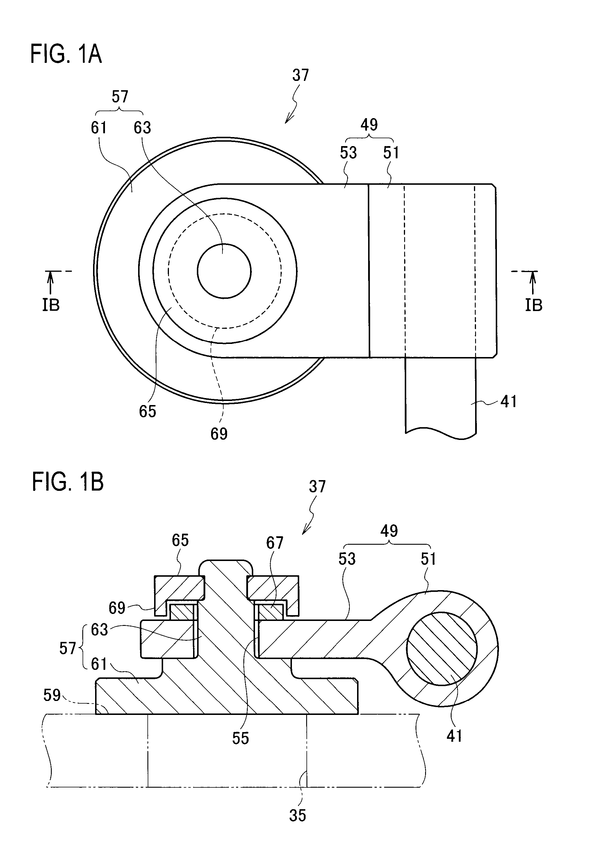
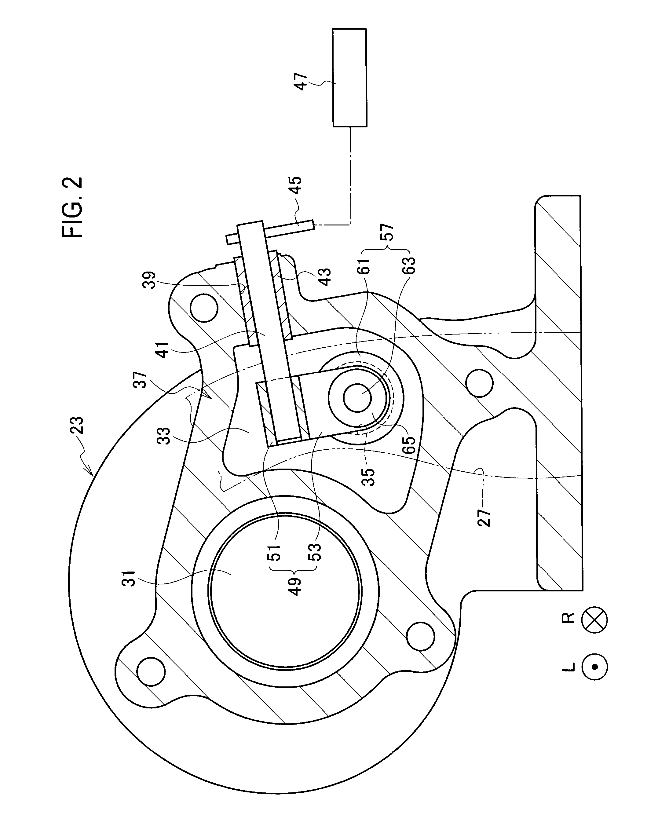
[0025]An embodiment of the present invention will be described with reference to FIG. 1A to FIG. 4. As shown in the drawings, “L” indicates a left direction while “R” indicates a right direction.

[0026]As shown in FIG. 4, a vehicle turbocharger 1 according to the embodiment is configured to supercharge (compress) air to be supplied to an engine (not shown) by using energy of an exhaust gas from the engine. The following is a specific configuration and the like of the vehicle turbocharger 1.

[0027]The vehicle turbocharger 1 includes a bearing housing 3. A pair of radial bearings 5 and a pair of thrust bearings 7 are provided inside the bearing housing 3. In addition, a rotor shaft (a turbine shaft) 9 extending in a right-left direction is rotatably provided to the multiple bearings 5 and 7. In other words, the rotor shaft 9 is rotatably provided to the bearing housing 3 through the multiple bearings 5 and 7.

[0028]A compressor housing 11 is provided on a right side of the bearing housin...


PUM


Abstract

In a waste gate valve, an annular spacer is provided between a washer and an attachment tongue in an axial direction of a valve shaft of a valve. The spacer is made of a graphite material. An annular guard wall is formed on a back surface of the washer in such a way as to surround the spacer.

Description

CROSS REFERENCE TO RELATED APPLICATIONS[0001]This application is a continuation application of International Application No. PCT / JP2013 / 056284, filed on Mar. 7, 2013, which claims priority to Japanese Patent Application No. 2012-053308, filed on Mar. 9, 2012, the entire contents of which are incorporated by references herein.BACKGROUND OF THE INVENTION[0002]1. Field of the Invention[0003]The present invention relates to a variable flow valve mechanism configured to open and close an opening of a gas passage to achieve a variable flow rate of an exhaust gas to be supplied to a turbine wheel side in a vehicle turbocharger.[0004]2. Description of the Related Art[0005]A bypass passage (one of gas passages) is usually formed inside a turbine housing of a vehicle turbocharger as a measure for preventing an excessive rise in boost pressure caused by the vehicle turbocharger. The bypass passage causes part of an exhaust gas to bypass a turbine wheel (turbine impeller). In other words, the b...

Claims


Application Information

Patent Timeline
Patent Type & Authority Applications(United States)
IPC IPC(8): F02B37/18F02D13/02
CPCF02D13/0242F02B37/183F02B37/186Y02T10/12
Inventor SEGAWA, KENICHI
Owner IHI CORP
Why Eureka
Try Eureka