Separation apparatus and method

Inactive Publication Date: 2007-08-09
SAFETY KLEEN EURO
View PDF11 Cites 11 Cited by
  • Summary
  • Abstract
  • Description
  • Claims
  • Application Information

AI Technical Summary

Benefits of technology

[0010] By directing the supply upwardly into the chamber, settling and separation is facilitated, especially if the supply also contains a substantial quantity of entrained gas, such as air. The vent means allows this gas to escape the chamber, rather than being retained.
[0050] Preferably, the connection means is adapted to permit relative rotation between the float and inlet assembly and a connected conduit. Advantageously, this allows the float and inlet assembly to self-level when the conduit is attached.

Problems solved by technology

A problem with such skimmers is that, as they rely on coalescence techniques to improve separation of the oil and water, they can block with fine solids and require changing or cleaning.
The time between cleaning or changing is difficult to gauge.
Generally, however, these units are hard to maintain and do not work successfully over a prolonged period.
A problem with such an arrangement is that injection of the supply causes churning which impedes the separation process.
This is a particular problem if the supply also comprises a large amount of entrained air.

Method used


Image

  • Separation apparatus and method
  • Separation apparatus and method
  • Separation apparatus and method

Examples


Embodiment Construction

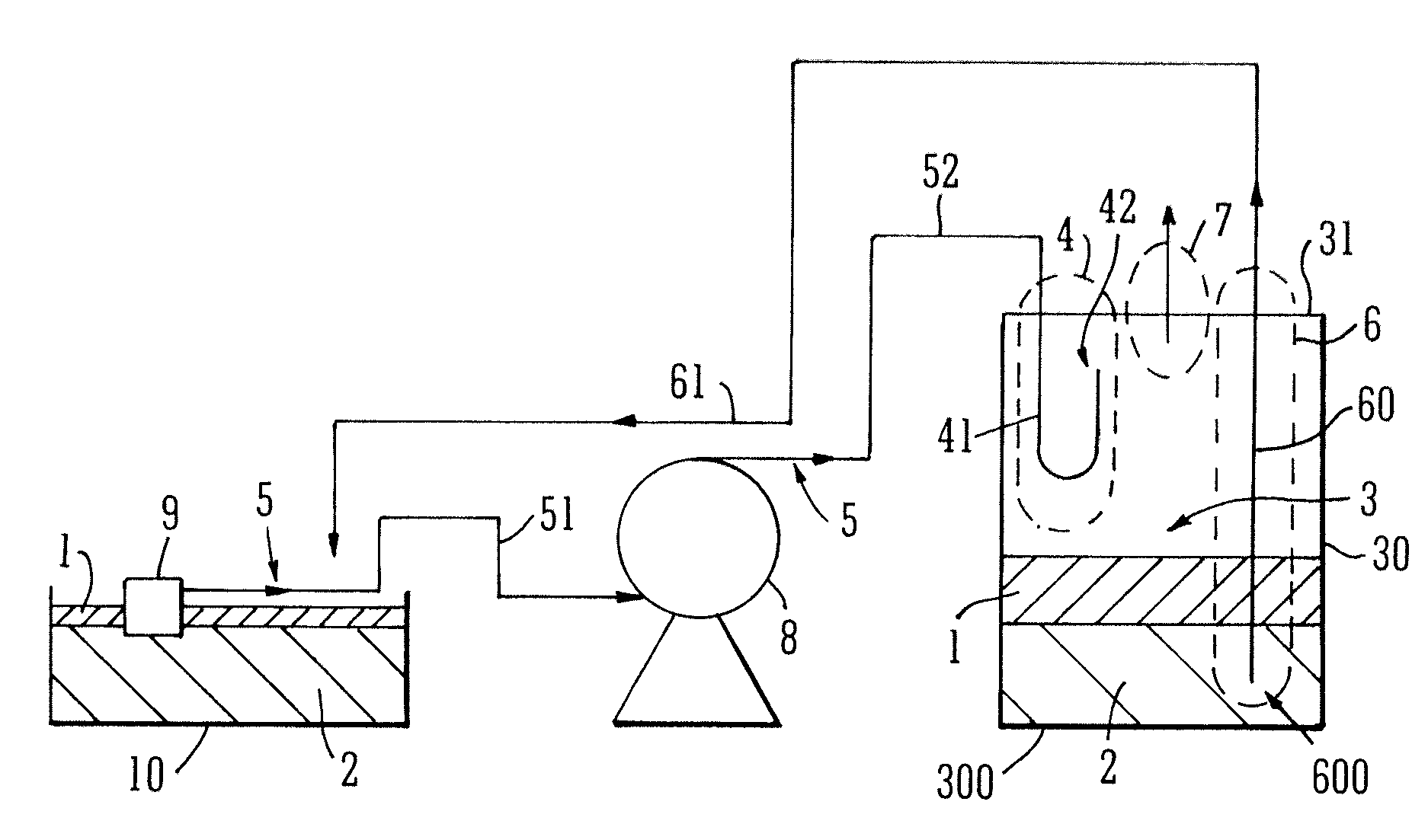
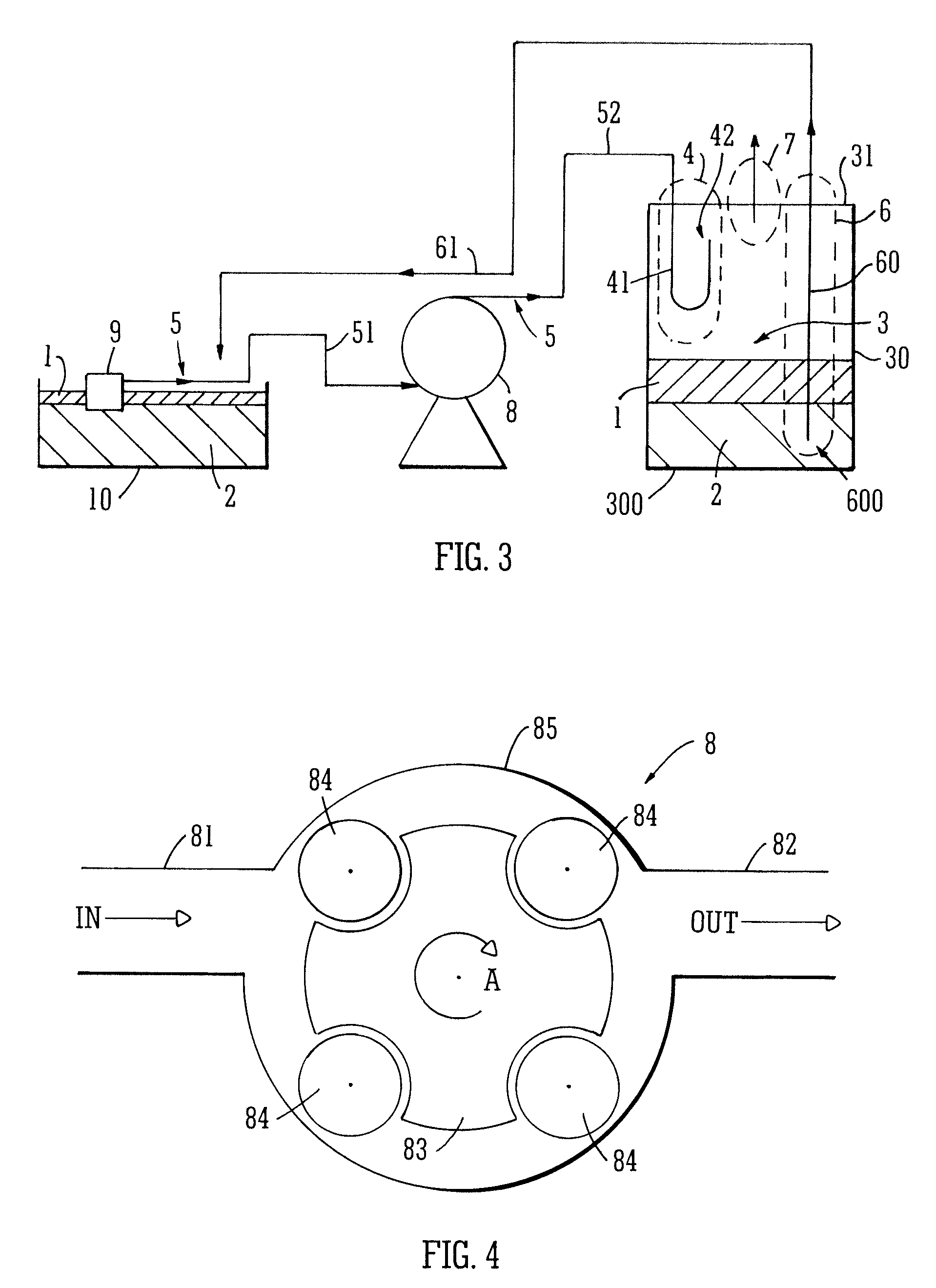
[0074] Referring now to FIG. 3, a separating apparatus (which may also be referred to as a separating system) embodying the invention comprises a drum 30 whose interior volume defines a separating chamber 3. The drum is closed by a head 31 (which may also be referred to as a lid or top) which is non-removable in this example. An inlet 4 is attached to the head 31 which provides a passage for material into the separation chamber 3. In other words the inlet is adapted to convey a supply 5 of material into the drum for separation. In this example the supply 5 into the drum 30 comprises a mixture of oil 1 and water 2. The apparatus includes a pump 8 arranged to pump this supply 5 to the inlet 4 from a sump 10. A quantity of oil 1 and water 2 has collected in this sump 10, with the oil 1 forming a layer floating on top of the water 2. The apparatus also comprises a floating pick up 9 connected to the pump 8 by means of a suitable conduit 51. This floating pick up 9 is arranged such that ...


PUM

PropertyMeasurementUnit
Lengthaaaaaaaaaa
Flow rateaaaaaaaaaa
Volumeaaaaaaaaaa

Abstract

Separating apparatus, for separating a substance from a liquid on which the substance can float, comprises: a separation chamber; an inlet adapted to convey a supply comprising the substance and the liquid into the separation chamber; and an outlet adapted to convey liquid collected in the separation chamber out of the separation chamber. The inlet is arranged such that, in use, the supply emerging from the inlet into the chamber is directed upwardly into the chamber, and the apparatus further comprises venting means arranged to convey gas out of the chamber. The apparatus may further comprise a floating pick up connected to a pump for pumping the supply to the separation chamber. In certain examples a non-floating pick up is used, comprising an elongate hollow body with a pick up inlet mouth in the form of a vertical slot extending along a length of the body.

Description

RELATED APPLICATIONS [0001] This application claims priority to British Patent Application No. 0602409.5, filed Feb. 7, 2006 and to European Patent Application No. 06256573.4, filed Dec. 22, 2006. FIELD OF THE INVENTION [0002] The present invention relates in general to apparatus for separating substances from liquids on which the substances can float, and in particular, although not exclusively, to cleaning apparatus known in the art as skimmers, for removing floating contaminants, such as oil, from the surface of another liquid, such as water or an aqueous solution. BACKGROUND TO THE INVENTION [0003] There are a wide variety of applications in which it is desirable or necessary to separate a floating substance from a liquid. The floating substance may, for example, be another liquid having a lower density. The floating substance may be an unwanted contaminant, or a useful material to be separated from the liquid beneath for use in some application. [0004] Skimmers are a type of se...

Claims


Application Information

Patent Timeline
IPC IPC(8): B01D35/00
CPCB01D17/0208B01D19/0042B01D17/0214
Inventor DAWES, RICHARDELLIS, STEVEN
Owner SAFETY KLEEN EURO
Why Eureka
Try Eureka