Rotational angle detecting sensor

a technology of rotating angle and detection sensor, which is applied in the direction of instruments, measurement apparatus components, generators/motors, etc., can solve the problems of increasing the cost of detector replacement, affecting the reliability of detection, and affecting the accuracy of detection, so as to reduce the possibility of pin breakage, reduce the stress applied, and reduce the repair cost

Inactive Publication Date: 2007-08-09
NTN CORP
View PDF9 Cites 7 Cited by
  • Summary
  • Abstract
  • Description
  • Claims
  • Application Information

AI Technical Summary

Benefits of technology

[0010] According to the present invention, there is provided a rotational angle detecting sensor comprising a cylindrical housing including an end wall at a first end thereof, a covering member covering a second open end of the housing, a rotary shaft extending through the end wall of the housing and having a large-diameter portion having a shoulder surface and rotatably received in the housing, a rotational angle detector disposed between an inner surface of the covering member and an end surface of the large-diameter portion of the rotary shaft, wherein an actuate groove is formed in an inner surface of the end wall of the housing concentrically with the rotary shaft and a stopper pin attached to the shoulder surface of the large-diameter portion of the rotary shaft so as to be movable in the groove, whereby the stopper pin abuts against circumferential ends of the groove, thereby limiting a rotational range of the stopper pin.
[0011] More specifically, the stopper pin is attached to the surface of the large-diameter portion of the rotary shaft opposite to the surface to which the rotational angle detector is mounted. With this arrangement, breakage of the pin is less likely to result in damage to the rotational angle detector.
[0012] Since the stopper pin is attached to the surface of the large-diameter portion opposite to the surface thereof to which the rotational angle detector is mounted, the rotational angle detector is less likely to be damaged even if the stopper pin breaks. Thus, even if the stopper pin breaks, what is needed is to replace the broken stopper pin only. This reduces repair costs.
[0013] By reducing the distance between the shoulder surface of the large-diameter portion of the rotary shaft, to which the stopper pin is mounted, and the inner surface of the end wall of the housing, in which the groove is formed in which the stopper pin is movable, it is possible to reduce the stress applied to the stopper pin when the pin abuts the circumferential ends of the groove, thereby reducing the possibility of breakage of the pin.

Problems solved by technology

The pieces may damage the rotational angle detector.
This increases the cost for replacement of the detector.
Thus, the stress applied to the pin can be reduced only to a certain extent, so that it is impossible to reliably prevent breakage of the stopper pin and thus damage to the rotational angle detector.
This makes it difficult to fit the detecting substrate on the protrusion with high positional accuracy, which in turn makes it difficult to detect the rotational angle with high accuracy.

Method used


Image

  • Rotational angle detecting sensor
  • Rotational angle detecting sensor
  • Rotational angle detecting sensor

Examples


Embodiment Construction

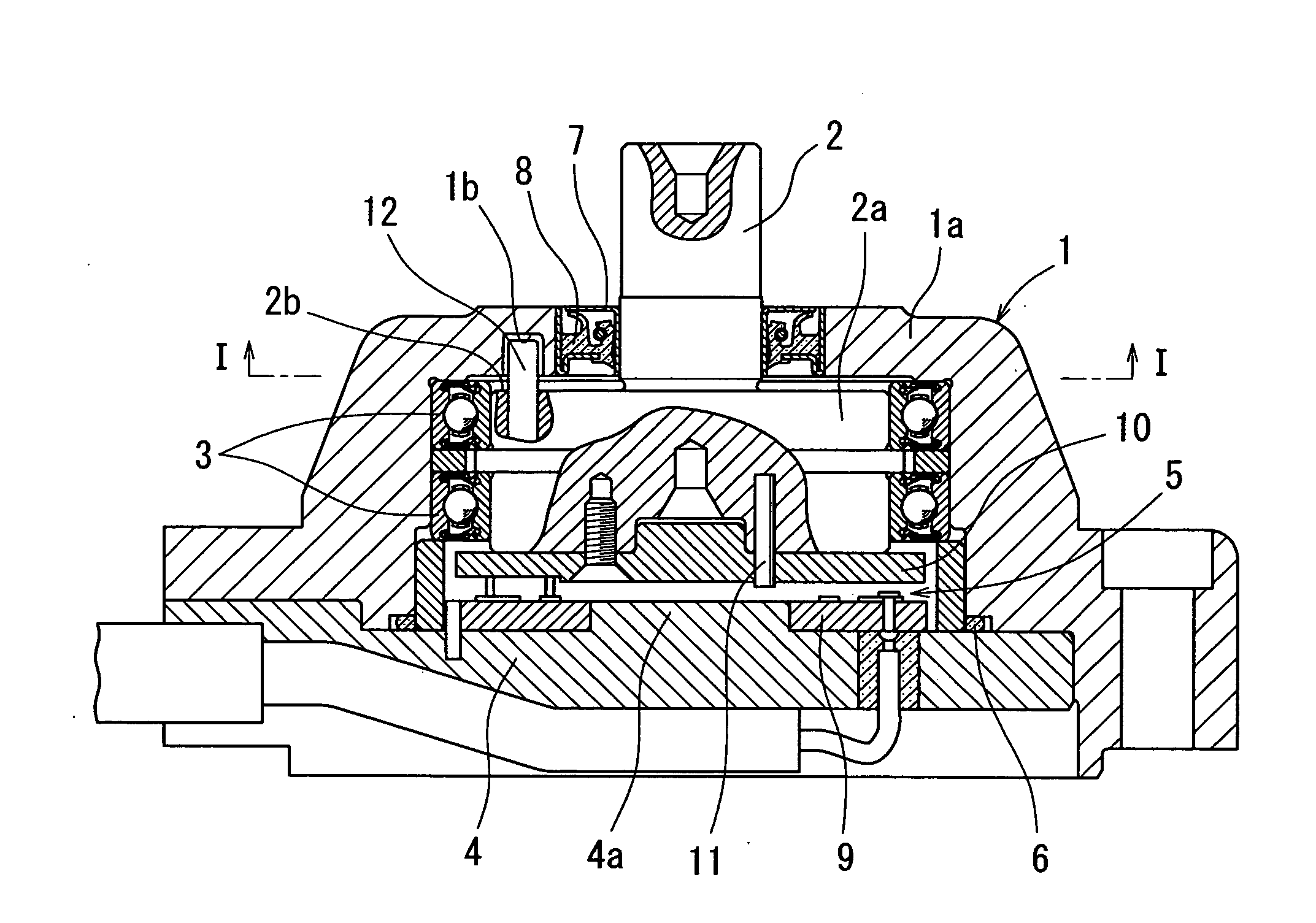
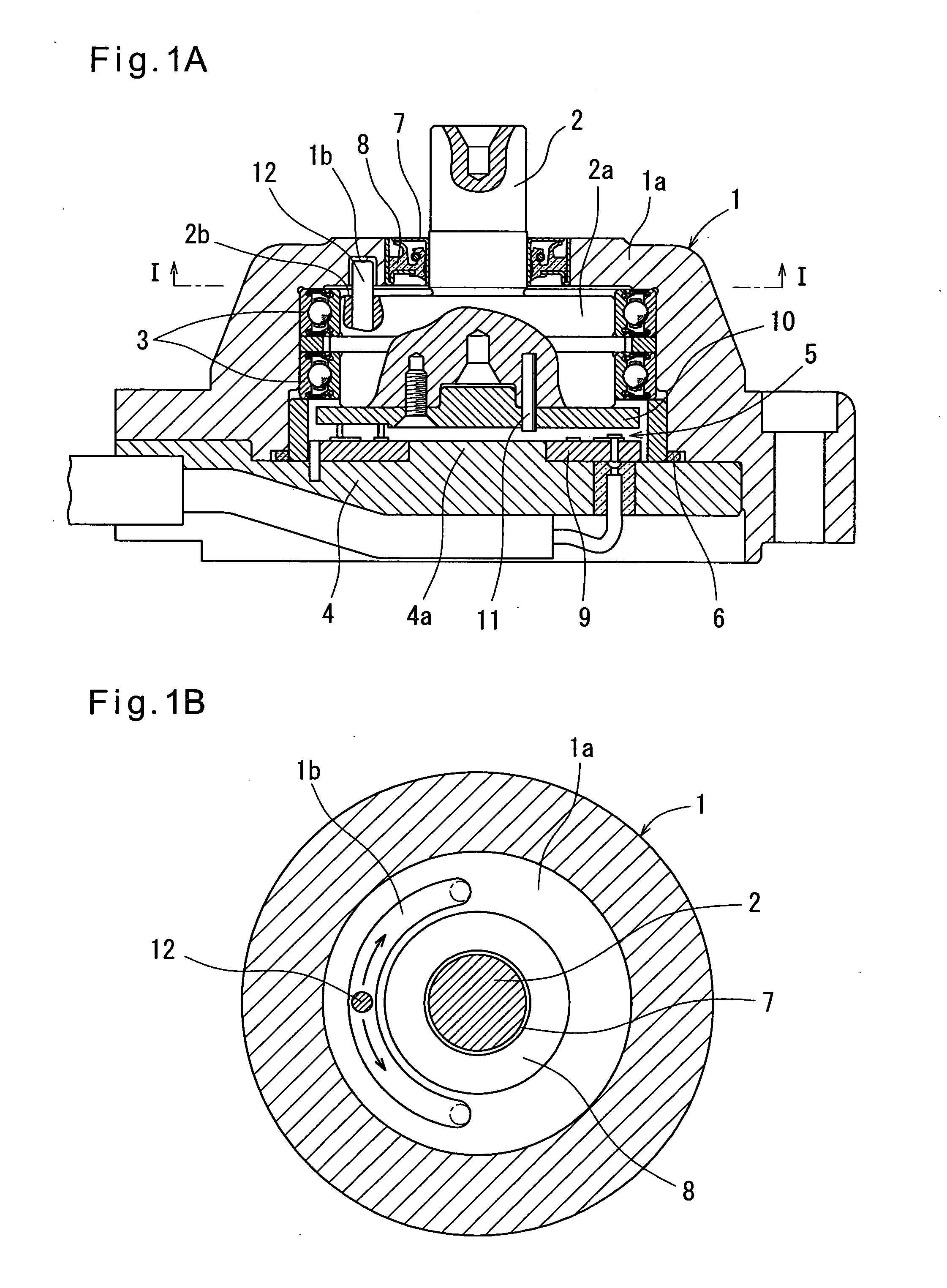
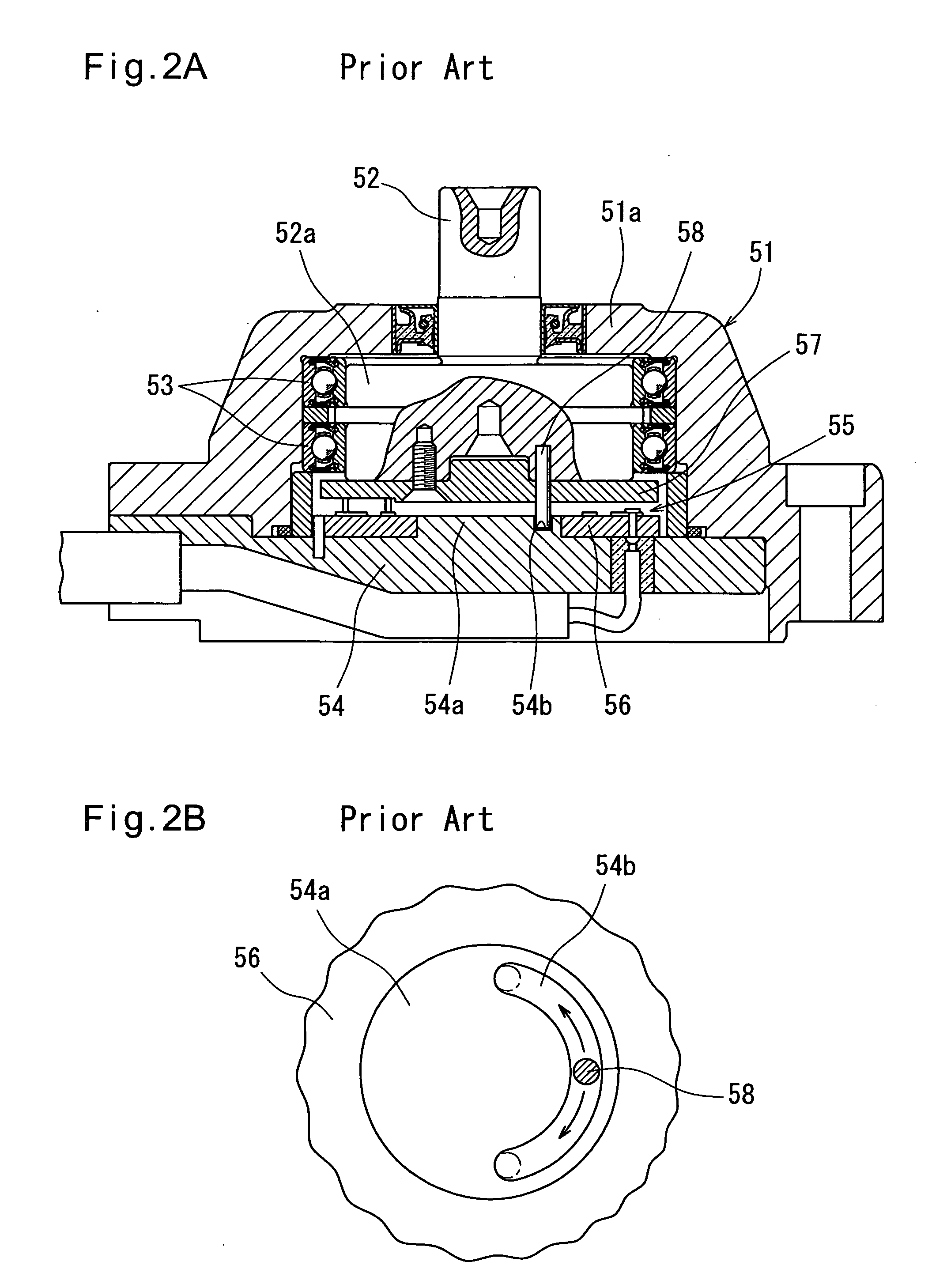
[0021] Now referring to the drawings, FIGS. 1A and 1B show a rotational angle detecting sensor embodying this invention. This rotational angle detecting sensor is basically of the same structure as the abovementioned conventional ones. As shown in FIG. 1A, this sensor includes a cylindrical housing 1 having an open end and an end wall 1a closing the other end thereof. The sensor further includes a rotary shaft 2 extending through the end wall 1a and having a large-diameter portion 2a at one end thereof. The large-diameter portion 2a is received in the housing 1 and rotatably supported by two ball bearings 3 preloaded in a stationary position. The housing has its open end covered by a covering member 4. A rotational angle detector 5 is disposed between the inner surface of the covering member 4 and the end surface of the large-diameter portion 2a. A lever (not shown) is fixed to the other end of the rotary shaft 2. The rotary shaft 2 is adapted to rotate via the lever when a machine ...


PUM


Abstract

A rotational angle detecting sensor has a cylindrical housing including an end wall at a first end thereof. A covering member covers the second open end of the housing. A rotary shaft extends through the end wall of the housing and includes a large-diameter portion having a shoulder surface and rotatably received in the housing. A rotational angle detector is disposed between the inner surface of the covering member and the end surface of the large-diameter portion of the rotary shaft. An actuate groove is formed in the inner surface of the end wall of the housing concentrically with the rotary shaft. A stopper pin is attached to the shoulder surface of the large-diameter portion of the rotary shaft so as to be movable in the groove. The stopper pin abuts against the circumferential ends of the groove, thereby limiting the rotational range of the stopper pin.

Description

BACKGROUND OF THE INVENTION [0001] The present invention relates to a rotational angle detecting sensor incorporated in construction machines or industrial machines, especially to a sensor to which high loads are applied. [0002] Such rotational angle detecting sensors include ones of which the rotary shaft has one end thereof received in a housing and rotatably supported so that the rotary shaft can rotate with high accuracy (for example, see Japanese utility model publication 2604100). [0003]FIGS. 2A and 2B show such a rotational angle detecting sensor. The rotational angle detecting sensor has a cylindrical housing 51 having an open end and an end wall 51a closing the other end thereof. The sensor further includes a rotary shaft 52 extending through the end wall 51a and having a large-diameter portion 52a at one end thereof. The large-diameter portion is received in the housing 51 and rotatably supported by two ball bearings 53 preloaded in a stationary position. The housing has i...

Claims


Application Information

Patent Timeline
Patent Type & Authority Applications(United States)
IPC IPC(8): H01L41/00H02N2/00G01B21/22
CPCG01D11/16G01D5/165
Inventor ITOMI, SHOJI
Owner NTN CORP
Why Eureka
Try Eureka