Transmission line transition
a technology of transmission line and transition line, which is applied in the direction of electrical equipment, multiple-port networks, coupling devices, etc., can solve the problems of increased manufacturing time and cost of the transition, and the inability to mass-production of the transition line, so as to achieve accurate and easy assembly, efficient coupling
- Summary
- Abstract
- Description
- Claims
- Application Information
AI Technical Summary
Benefits of technology
Problems solved by technology
Method used
Image
Examples
first embodiment
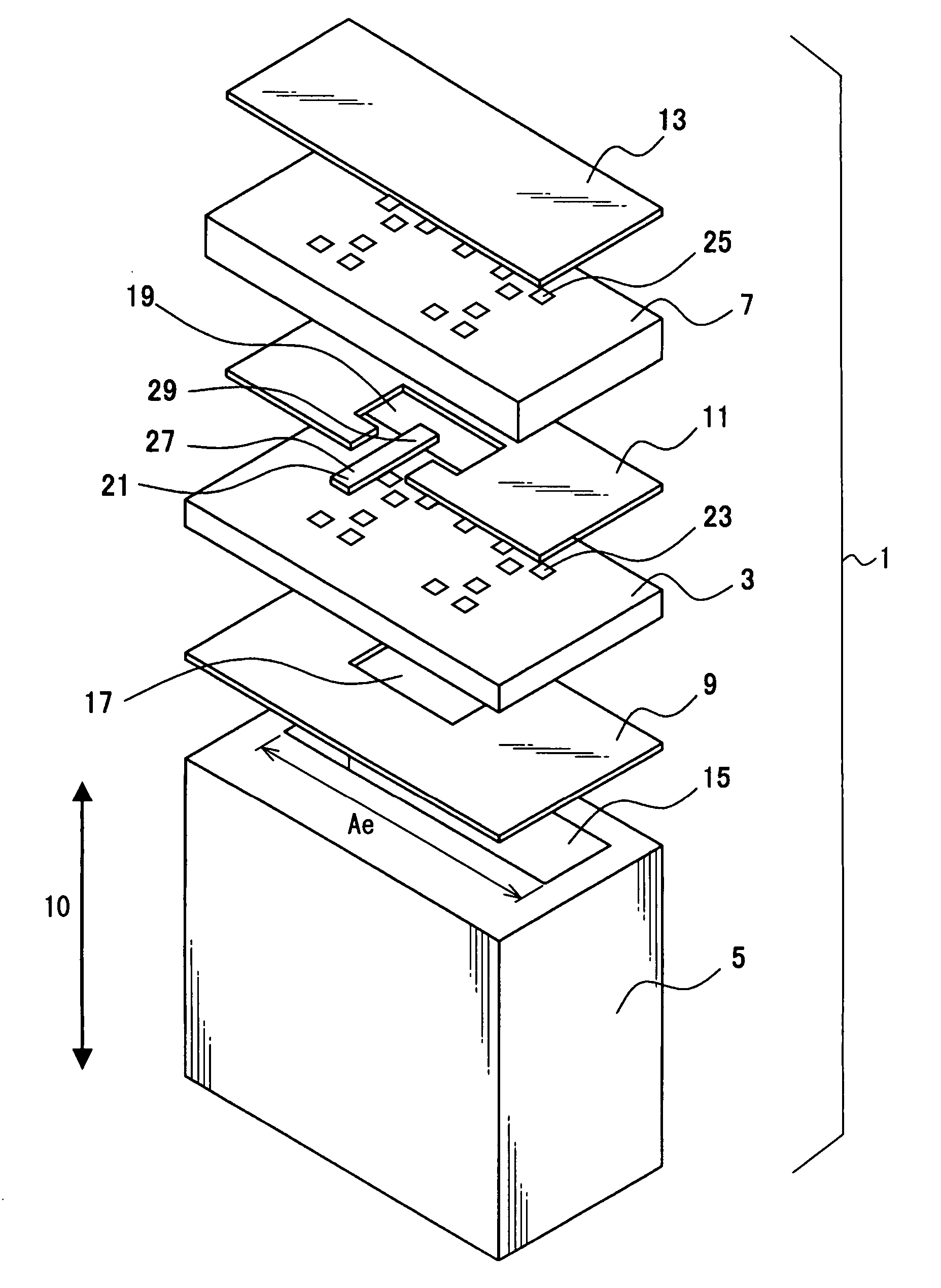
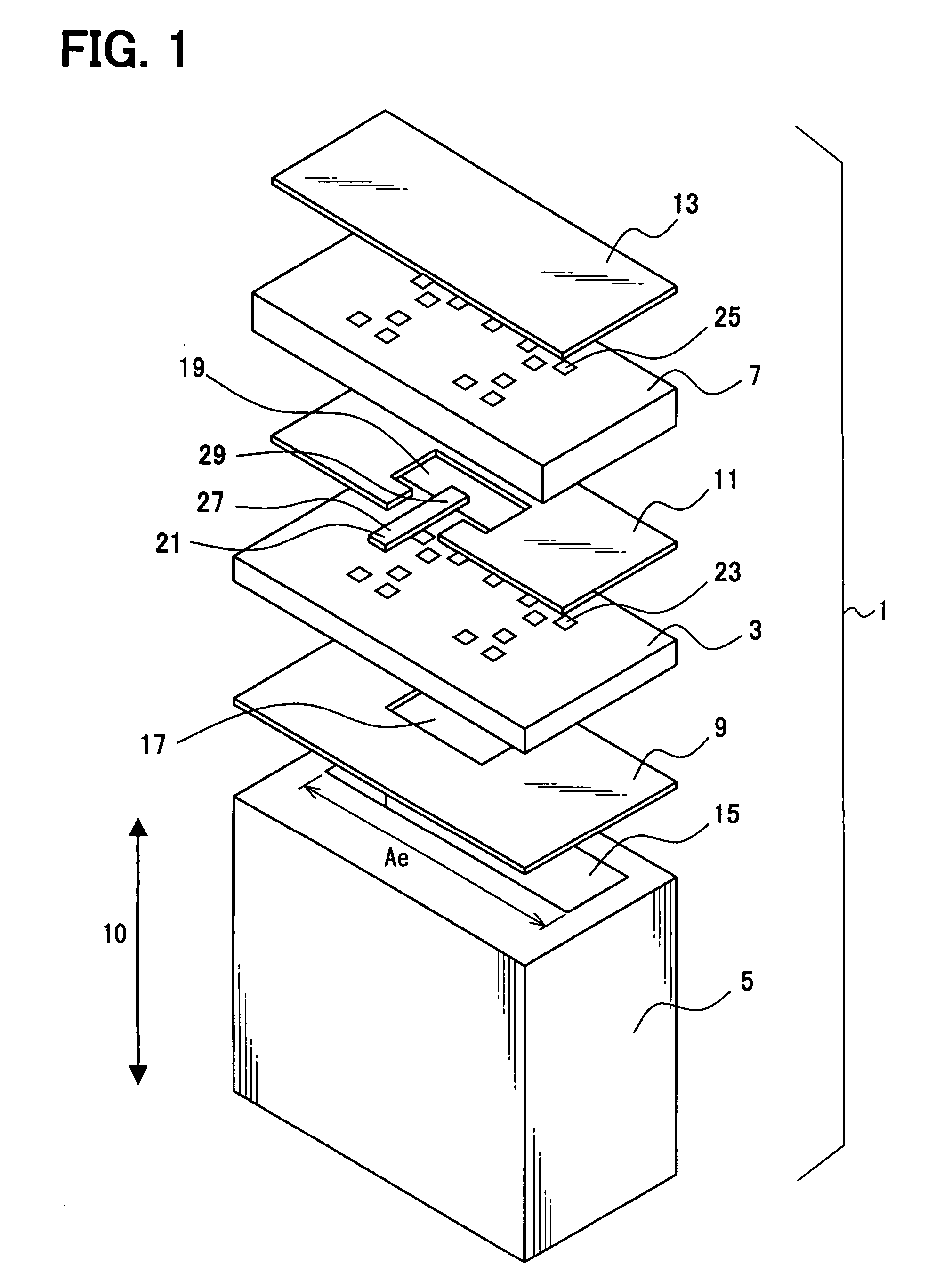
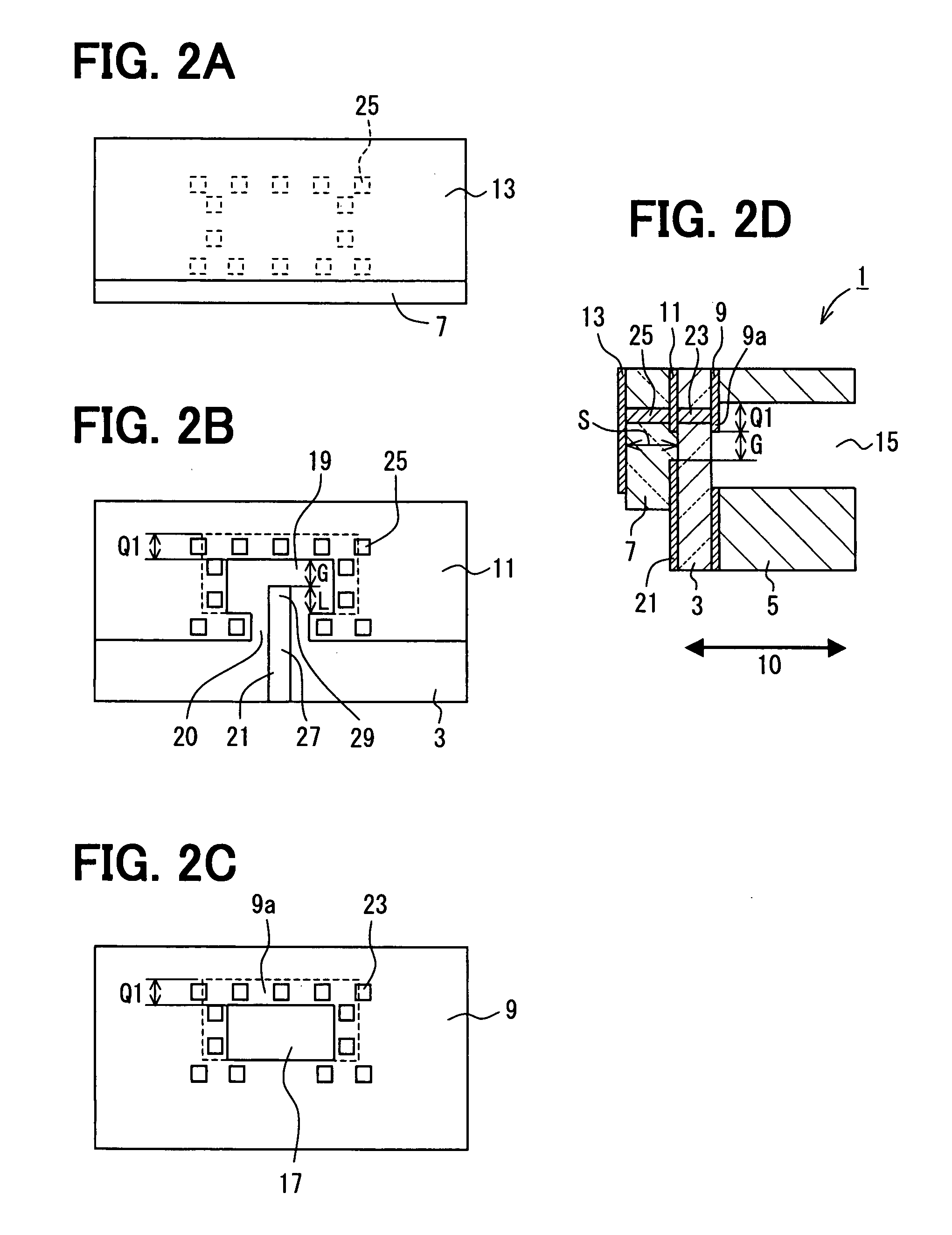
[0023] A planar line-to-waveguide transition 1 for coupling electromagnetic energy between a planar line and a waveguide is shown in FIGS. 1 and 2A-2D. The transition 1 includes a first dielectric substrate 3, a waveguide tube 5, a second dielectric substrate 7, and first, second, and third ground planes 9, 11, 13.
[0024] The first dielectric substrate 3 may be, for example, made of alumina. The first dielectric substrate 3 has a first surface on which the first ground plane 9 is disposed and a second surface on which the second ground plane 11 is disposed.
[0025] The waveguide tube 5 may be, for example, a hollow rectangular tube made of aluminum. The waveguide tube 5 has a hollow interior 15 with a rectangular cross section. One open end of the waveguide tube 5 is fixedly secured to the first dielectric substrate 3 through the first ground plane 9 by brazing, screws, or the like. The waveguide tube 5 has a longitudinal direction 10 shown in FIG. 1 and the electromagnetic energy pr...
second embodiment
[0045] The second embodiment of the present invention is shown in FIGS. 3A and 3B. In the second embodiment, a first ground plane 31 has a project portion 31a projecting from a bottom edge of an interior 37 of a waveguide tube 35 by a distance Q2. The tip of an antenna 39 and a bottom edge of an opening 33 of the first ground plane 31 are spaced from each other by the distance L.
[0046] The distance L is kept constant even when the waveguide tube 35 is improperly fixed to the project portion 31a of the first ground plane 31. Thus, the project portion 31a serves as the margin for error in fixing the waveguide tube 35 to the first ground plane 31 and allows the transition 1 having the desired coupling characteristic to be mass-produced.
third embodiment
[0047] The third embodiment of the present invention is shown in FIGS. 4A and 4B. In the third embodiment, a first ground plane 41 has a project portion 41a projecting from a top edge of an interior 47 of a waveguide tube 45 by a distance Q1. A second ground plane 43 has a project portion 43a projecting from a top edge of the interior 47 by a distance Q3 greater than the distance Q1. As a result, a distance between the second ground plane 43 and an antenna 49 of the third embodiment is smaller than that between the second ground plane 11 and the antenna 29 of the first embodiment.
[0048] In such an approach, double resonance occurs in the dielectric waveguide so that frequency characteristics of propagation of the electromagnetic energy become broadband characteristics. Further, a distance G between the antenna 49 and the first ground plane 41 is kept constant even when the waveguide tube 45 is improperly fixed to the project portion 41a of the first ground plane 41. Thus, the proje...
PUM
 Abstract
Description
Claims
Application Information
 - R&D
- Intellectual Property
- Life Sciences
- Materials
- Tech Scout
- Unparalleled Data Quality
- Higher Quality Content
- 60% Fewer Hallucinations
Browse by: Latest US Patents, China's latest patents, Technical Efficacy Thesaurus, Application Domain, Technology Topic, Popular Technical Reports.
© 2025 PatSnap. All rights reserved.Legal|Privacy policy|Modern Slavery Act Transparency Statement|Sitemap|About US| Contact US: help@patsnap.com


