Mobile device having RFID system

a mobile device and radio frequency identification technology, applied in the direction of near-field systems using receivers, instruments, burglar alarm mechanical actuation, etc., can solve the problems of reducing and affecting the service life of the mobile communication terminal. , to achieve the effect of preventing the input of a transmission carrier leakage and preventing the size increase of the mobile communication terminal

Inactive Publication Date: 2007-08-09
SAMSUNG ELECTRONICS CO LTD
View PDF20 Cites 12 Cited by
  • Summary
  • Abstract
  • Description
  • Claims
  • Application Information

AI Technical Summary

Benefits of technology

[0020]The present invention provides a mobile communication terminal having an RFID system, which is capable of preventing input of a transmission carrier leakage into a reception circuit.
[0021]The present invention also provides a mobile communication terminal having an RFID system, which is capable of preventing size increase of the mobile communication terminal due to mounting of a plurality of antennas.

Problems solved by technology

In particular, when the RFID system is applied to the mobile communication terminal, it is difficult to install a plurality of antennas due to space constraints.
Therefore, it is practically impossible to acquire an accurate reception signal from the RFID tag 30, and degradation of signal and direct current (DC) offset occur.
Therefore, it is difficult to increase the size of the signal.
Although the difference between the bands for an RFID wireless signal and the mobile communication signal is relatively small, it is hard for the mobile communication antenna, which is designed for narrow band, to transmit and receive an RFID wireless signal.

Method used


Image

  • Mobile device having RFID system
  • Mobile device having RFID system
  • Mobile device having RFID system

Examples


Embodiment Construction

[0052]Hereinafter, the present invention will be described in detail with reference to the drawings.

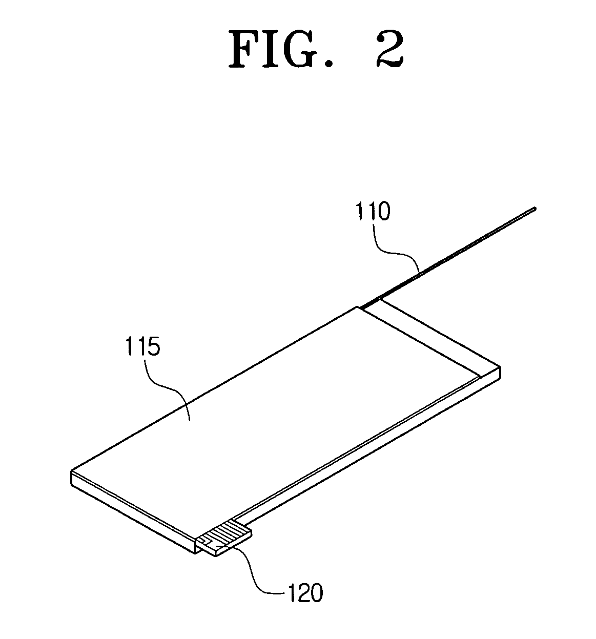
[0053]FIG. 2 is a perspective view of an antenna area of a mobile communication terminal according to a first exemplary embodiment of the present invention. As shown, the mobile communication terminal may include a main antenna 110, a ground 115 and an RFID reception antenna 120.

[0054]The main antenna 110 may be used as a mobile communication antenna which transmits and receives wireless communication signal when the mobile communication terminal operates in a basic communication mode. Alternatively, the main antenna 110 may be used as an RFID transmission antenna to transmit an RFID signal to the RFID tag.

[0055]The main antenna 110 may be implemented as any adequate antenna. In the first exemplary embodiment of the present invention, a whip antenna of a bar configuration will be used as the main antenna 110. The whip antenna is generally used in mobile communication terminals, and in...


PUM


Abstract

A mobile communication terminal has a radio frequency identification (RFID) system to read information from RFID tags at predetermined distances. An RFID transmission antenna to transmit or receive a wireless signal for mobile communication to/from a base station, or transmit wireless signal to the RFID tag, and an RFID reception antenna to receive RFID wireless signal transmitted from the RFID tag. Accordingly, ingress of the RFID transmission carrier leakage to the RFID reception circuit can be prevented. Additionally, a small size antenna such as a chip ceramic antenna is used exclusively for RFID reception, and the RFID reception antenna is also used as a mobile communication antenna. As a result, the mobile communication terminal can be compact-sized, the size of transmission signal can be increased, and dynamic range increases without having to increase the sensitivity of the RFID tag, to extend the communication distance.

Description

CROSS-REFERENCE TO RELATED APPLICATION[0001]This application claims priority from Korean Patent Application No. 10-2006-0010502, filed Feb. 3, 2006, in the Korean Intellectual Property Office, the entire contents of which are incorporated herein by reference.BACKGROUND OF THE INVENTION[0002]1. Field of the Invention[0003]Apparatuses consistent with the present invention relate to a mobile device having a radio frequency identification (RFID) system, and more particularly, to a mobile device having an RFID system which is capable of preventing input of transmission carrier leakage to a receiver circuit, and which can be provided in a compact size.[0004]2. Description of the Prior Art[0005]An RFID system generally includes a reader, an antenna, an electronic tag, a server, and a network. The reader reads out or stores information from or to the electronic tag, and the antenna exchanges data with the electronic tag according to predefined frequencies and protocols.[0006]With the combin...

Claims


Application Information

Patent Timeline
Patent Type & Authority Applications(United States)
IPC IPC(8): G08B13/14H05K11/00G06K7/00G06K17/00H04B1/3822H04B1/40H04B1/59H04B5/02
CPCG06K7/0008H01Q1/2216H01Q1/242H04M1/7253H01Q9/42H04B1/3805H01Q9/0421H04M1/72412H01Q1/24H04B1/40H04B5/02
Inventor KIM, YONG-JINKIM, YOUNG-EILLEE, SEONG-SOOYOON, HYUNG-MINYOON, ICK-JAEKOO, JI-HUN
Owner SAMSUNG ELECTRONICS CO LTD
Why Eureka
Try Eureka