
Communication method, communication device, and computer program

a communication device and computer program technology, applied in the field of communication methods and communication apparatuses, can solve problems such as hardware limitation, increase (latency increase) of round trip time (rtt), and achieve the effect of excellent communication method and communication apparatus

Active Publication Date: 2007-08-09
SONY CORP
View PDF5 Cites 2 Cited by
  • Summary
  • Abstract
  • Description
  • Claims
  • Application Information

AI Technical Summary

Benefits of technology

The present invention is a communication method and apparatus in a network with multiple stations. It uses beacons to set a reception state and detect signals from other stations to avoid collisions. The invention also allows for minimum data transfer with latency as small as possible based on the volume of data transfer. This results in an efficient communication system.

Problems solved by technology

When the above communication control is performed, the following problems exist.
The accumulation of data within the transmission and reception unit causes an increase (increase of latency) in round trip time (RTT) between the reception and transmission units at an application level, and there occurs a problem that throughput reaches a ceiling when ARQ using a sliding window is performed.
Moreover, in order to avoid an overflow, a buffer as big as one capable of sustaining the data accumulation within the communication station STA1 that is the transmission station is needed, which causes a problem of limitation regarding hardware.
Although the accumulation of data in the transmission station STA1 is certainly resolved, the reception unit is uselessly operated in the communication station STA0 that is the reception side and a problem remains from a viewpoint of power consumption since there exist a number of idle periods (period shown with an arrow in FIG. 30F) in which data reception is not performed actually though the reception unit keeps operating.
Further, although broadcast information transmitted and received in an infrastructure mode can be conveyed even if a communication station MT receives beacon information only once in several times, it is necessary to keep the transmission of the broadcast information waiting from the time when data is passed from an upper layer until countdown is ended when an access point AP intends to broadcast the data passed from the upper layer, and there occurs such a problem that a delay until the broadcast information is actually transmitted becomes large.

Method used


Image

  • Communication method, communication device, and computer program
  • Communication method, communication device, and computer program
  • Communication method, communication device, and computer program

Examples


Embodiment Construction

[0056] Hereinafter, an embodiment of the present invention is explained referring to FIGS. 1 through 25.

[0057] In this embodiment, a wireless propagation path of communication is assumed, and in which a network is formed among a plurality of devices using a single transmission medium (not a case in which a link is separated based on a frequency channel). However, even if a plurality of frequency channels exist as the transmission medium, a similar thing can be said. In addition, store-and-forward type traffic is assumed as the communication in this embodiment and information is transferred by a unit of packet.

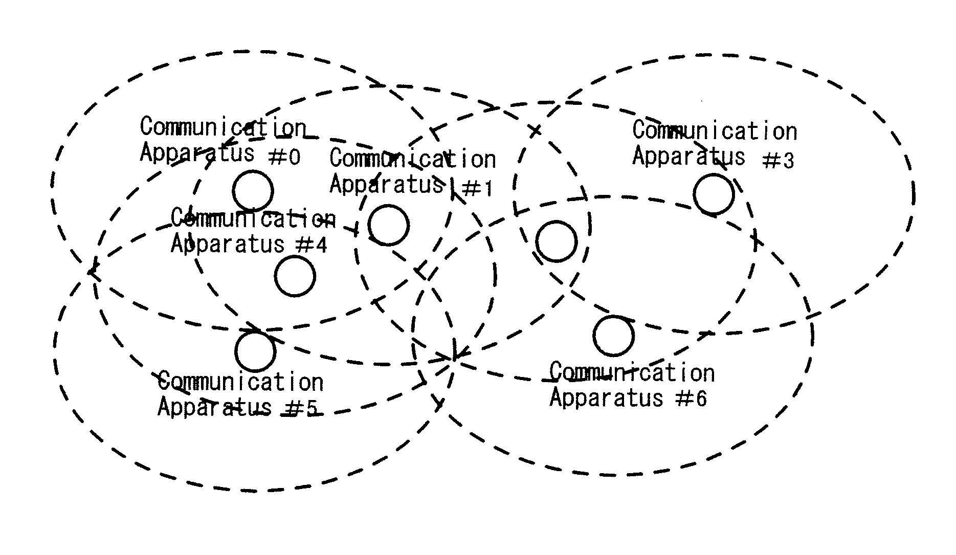
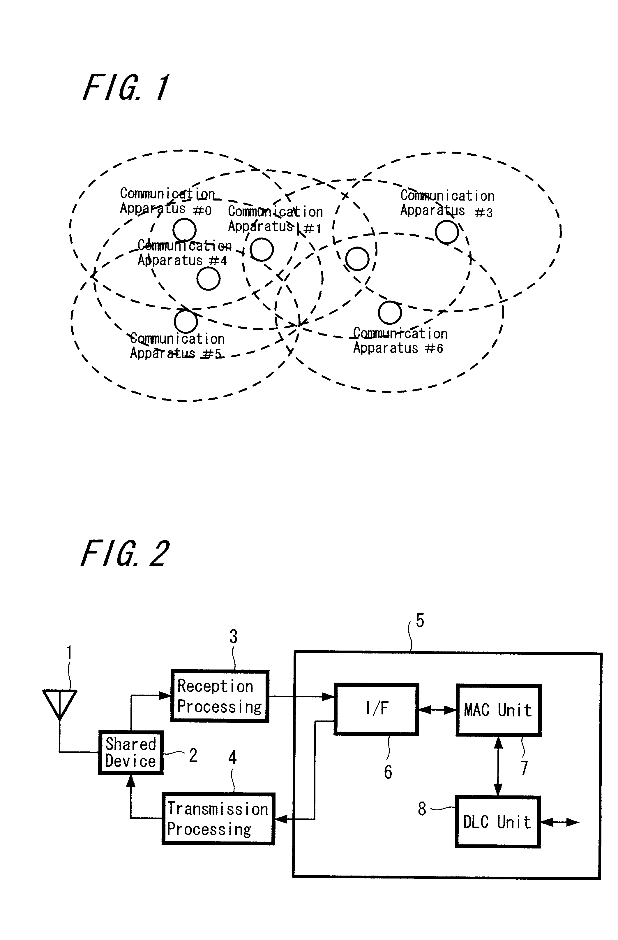
[0058] An example of arrangement of communication apparatuses constituting a wireless communication system according to an embodiment of the present invention is shown in FIG. 1. In this wireless communication system, no specific control station is disposed, each communication apparatus operates in an autonomously distributed manner, and what is called an ad hoc network is fo...


PUM


Abstract

In order to solve a problem of an accumulation on the transmission side, a delay on the reception side, and the like at the time of transmission in a communication system such as a wireless LAN system, each communication station in a network transmits a beacon in which information with respect to the network is written and sets a state in which a reception operation is performed during periods of time before and after the transmission of the beacon signal when performing access control not to make communication timing of a packet collide with that of another station by detecting a signal transmitted from another station. With performing such processing, a system can be formed based on minimum level of transmission and reception operation when transmission and reception data does not exist in each communication station in the network, and also a data transfer can be performed with latency as small as possible in a minimum necessary level of transmission and reception operation by making a transition of a transmission and reception state in accordance with a fluctuating volume of transmission and reception data.

Description

CROSS REFERENCE TO RELATED APPLICATIONS [0001] This application is a continuation of and is based upon and claims the benefit of priority under 35 U.S.C. § 120 of U.S. application Ser. No. 10 / 544,107 filed May 24, 2006, which is a National Stage of PCT / JP04 / 01027, filed on Feb. 3, 2004, all of which claim priority to Japanese Patent Application No. 2003-026462, filed on Feb. 3, 2003. The contents of each of these documents are incorporated herein by reference.TECHNICAL FIELD [0002] The present invention relates to a communication method and a communication apparatus suitable for applying to a wireless LAN (Local Area Network: local information and communication network) system which performs data communication and the like, for example. Particularly, the present invention relates to a communication method and a communication apparatus suitable for applying to a case where an autonomous distributed type network not having a controlling and controlled relation between a master station...

Claims


Application Information

Patent Timeline
Patent Type & Authority Applications(United States)
IPC IPC(8): H04B7/00H04B7/15H04B7/24H04L7/00H04L12/28H04W24/00H04W28/00H04W74/04H04W74/08H04W84/10H04W84/12H04W84/18
CPCH04W74/002H04W74/0808H04W84/12H04W72/12H04W72/0493H04W72/02H04W40/244H04W72/048H04W84/18H04W72/51H04W72/53H04W72/0446H04W84/20
Inventor SAKODA, KAZUYUKI
Owner SONY CORP
Learn More