Eureka AIR delivers breakthrough ideas for toughest innovation challenges, trusted by R&D personnel around the world.

Insertable strain gauge spanner

Active Publication Date: 2007-08-16
HSIEH CHIH CHING
View PDF0 Cites 5 Cited by
  • Summary
  • Abstract
  • Description
  • Claims
  • Application Information

AI Technical Summary

Benefits of technology

[0005] Accordingly, the primary object of the present invention is to provide an insertable strain gauge spanner, wherein the driving head is adjustable by rotating through 90 degrees and then inserted into the inserting opening of the a handle of the spanner. As a result the twisting force will not be transferred to the sensing end of the strain gauge so as to protect the strain gauge from being destroyed.
[0006] To achieve above objects, the present invention provides an insertable strain gauge spanner which comprises a spanner body having a rod body and a driving head insertable into the rod body; the rod body having a handle and an inserting opening at one end thereof; the inserting opening can be received the driving head; the rod body being installed with a strain gauge; a lower end of the rod body being formed as an inserting opening; the inserting opening being in contact with the strain gauge; thereby the twisting force from the driving head can be transferred to a sensing end of the strain gauge; the twisting force being displayed in a window of the strain gauge; and the driving head having an inserting end having a shape corresponding to that of the inserting opening; and the orientation of the driving head with respect to the rod body is adjusted by adjusting the orientation of the inserting end with respect to the driving opening so as to avoid a great twisting force is transferred to the strain gauge from the driving head.

Problems solved by technology

If the twisting force is over a predetermined value, the strain gauge is possibly destroyed.
Thus the use of the strain gauge spanner is limited.
If the user drives an element along another direction, the strain gauge cannot measure the twisting force.
Thereby the operation is inconvenient.
Thus, it is not practical.

Method used


Image

  • Insertable strain gauge spanner
  • Insertable strain gauge spanner
  • Insertable strain gauge spanner

Examples


Embodiment Construction

[0012] In order that those skilled in the art can further understand the present invention, a description will be provided in the following in details. However, these descriptions and the appended drawings are only used to cause those skilled in the art to understand the objects, features, and characteristics of the present invention, but not to be used to confine the scope and spirit of the present invention defined in the appended claims.

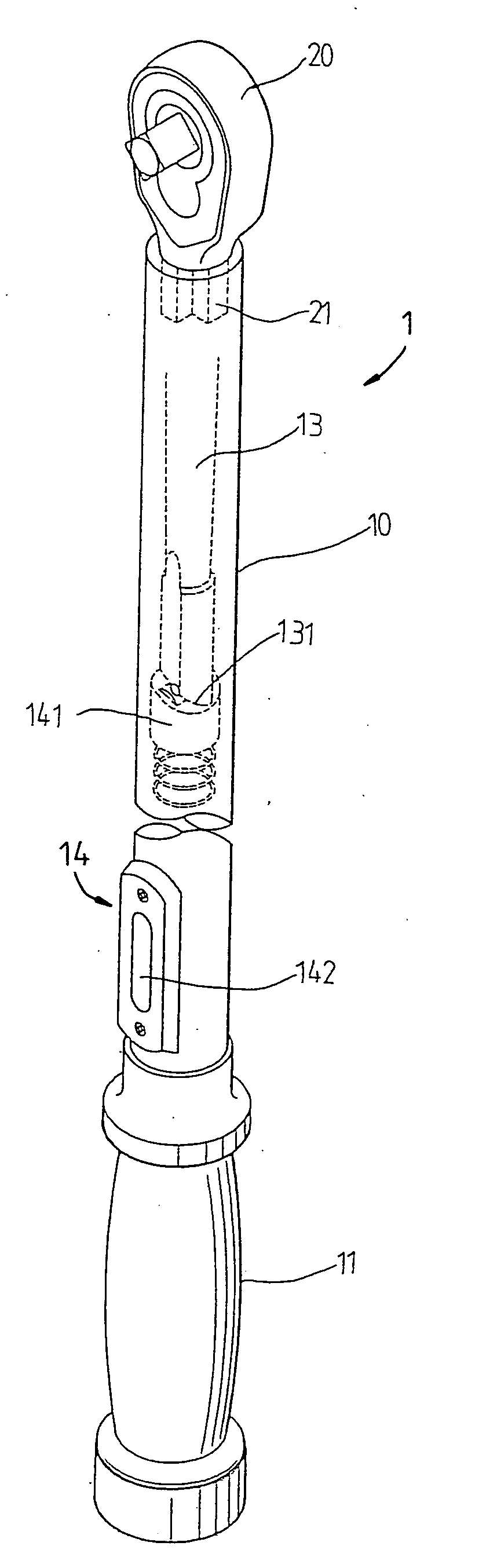
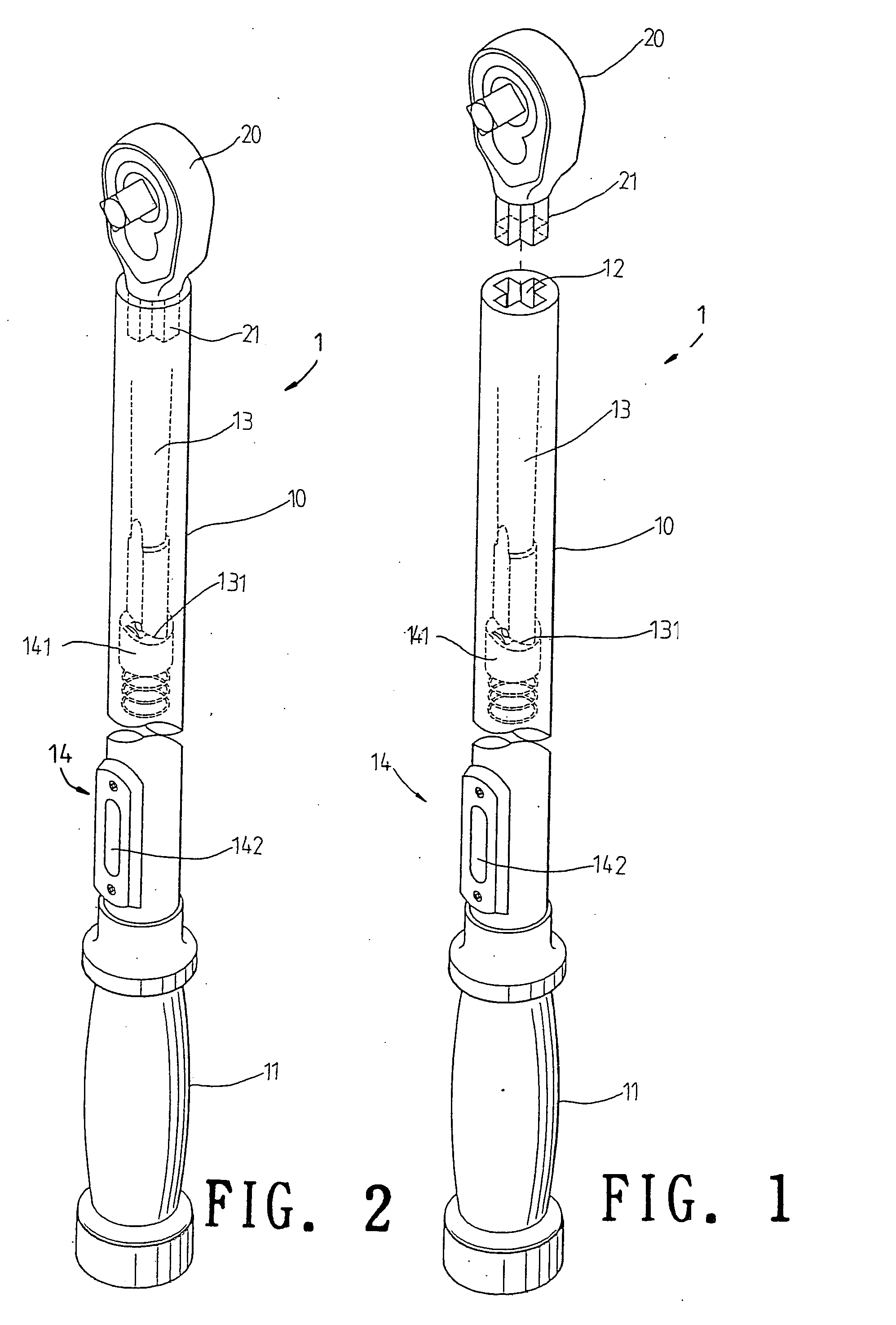
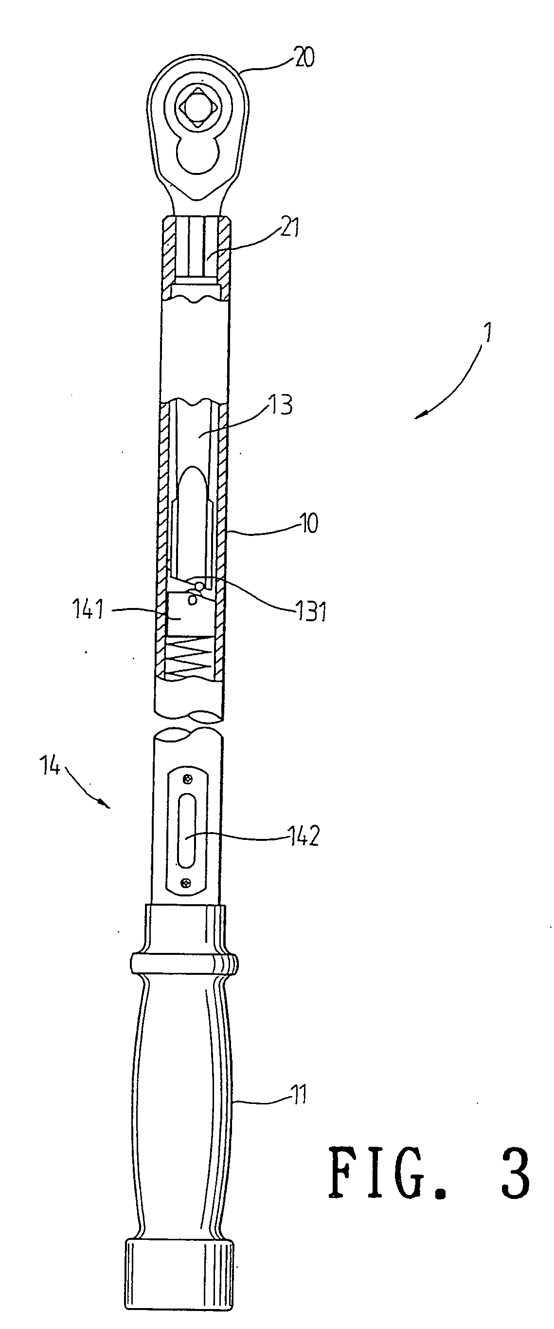
[0013] With reference to FIGS. 1 to 3, the present invention is illustrated. The present invention has the following elements.

[0014] A spanner body 1 has the effect of measuring twisting forces. The spanner body 1 has a rod body 10 and a driving head 20 insertable into the rod body 10.

[0015] The rod body 10 has a handle 11 and an inserting opening 12 at one end thereof. The inserting opening 12 can receive the driving head 20. In this the present invention, the inserting opening 12 has a cruciform shape. However this is not used to confine the ...


PUM


Abstract

An insertable strain gauge spanner which comprises a spanner body having a rod body and a driving head insertable into the rod body; the rod body having a handle and an inserting opening at one end thereof; the inserting opening can be received the driving head; the rod body being installed with a strain gauge; a lower end of the rod body being formed as an inserting opening; the inserting opening being in contact with the strain gauge; thereby the twisting force from the driving head can be transferred to a sensing end of the strain gauge; the twisting force being displayed in a window of the strain gauge; and the driving head having an inserting end with a shape corresponding to that of the inserting opening; and the orientation of the driving head with respect to the rod body is adjustable.

Description

FIELD OF THE INVENTION [0001] The present invention relates to spanners, and in particular to an insertable strain gauge spanner, wherein the driving head is adjustable by rotating through 90 degrees and then inserted into the inserting opening of a handle of the spanner. As a result the twisting force will not be transferred to the sensing end of the strain gauge so as to protect the strain gauge from being destroyed. BACKGROUND OF THE INVENTION [0002] Spanners with strain gauges are more and more popular because it can measure the strains in operation so that the user can determine the applied force and to control the size of the applied force not to be too large so as to destroy the element to be released. [0003] There are many kinds of spanners with strain gauges are developed. In one prior art, disclosed in Taiwan Patent No. 284306, the strain gauge spanner is installed with a strain gauge for determining the strain gauge in operation so that the user can determine that the ele...

Claims


Application Information

Patent Timeline
IPC IPC(8): G01L3/18
CPCG01L5/24B25B23/1425
Inventor HSIEH, CHIH-CHING
Owner HSIEH CHIH CHING
Why Eureka
Eureka Blog
Learn More