Cooking appliance

a technology for cooking appliances and cooking oil, which is applied in the field of cooking appliances, can solve problems such as the dispensing of drippings from food articles

Inactive Publication Date: 2007-08-16
AAC TRADE LTD
View PDF52 Cites 19 Cited by
  • Summary
  • Abstract
  • Description
  • Claims
  • Application Information

AI Technical Summary

Problems solved by technology

However, such an arrangement provides a cantilever support for the two cooking plates, and therefore is not only unreliable for maintaining the two plates in a space parallel relationship, but is also subject to tremendous strai

Method used


Image

  • Cooking appliance
  • Cooking appliance
  • Cooking appliance

Examples


Embodiment Construction

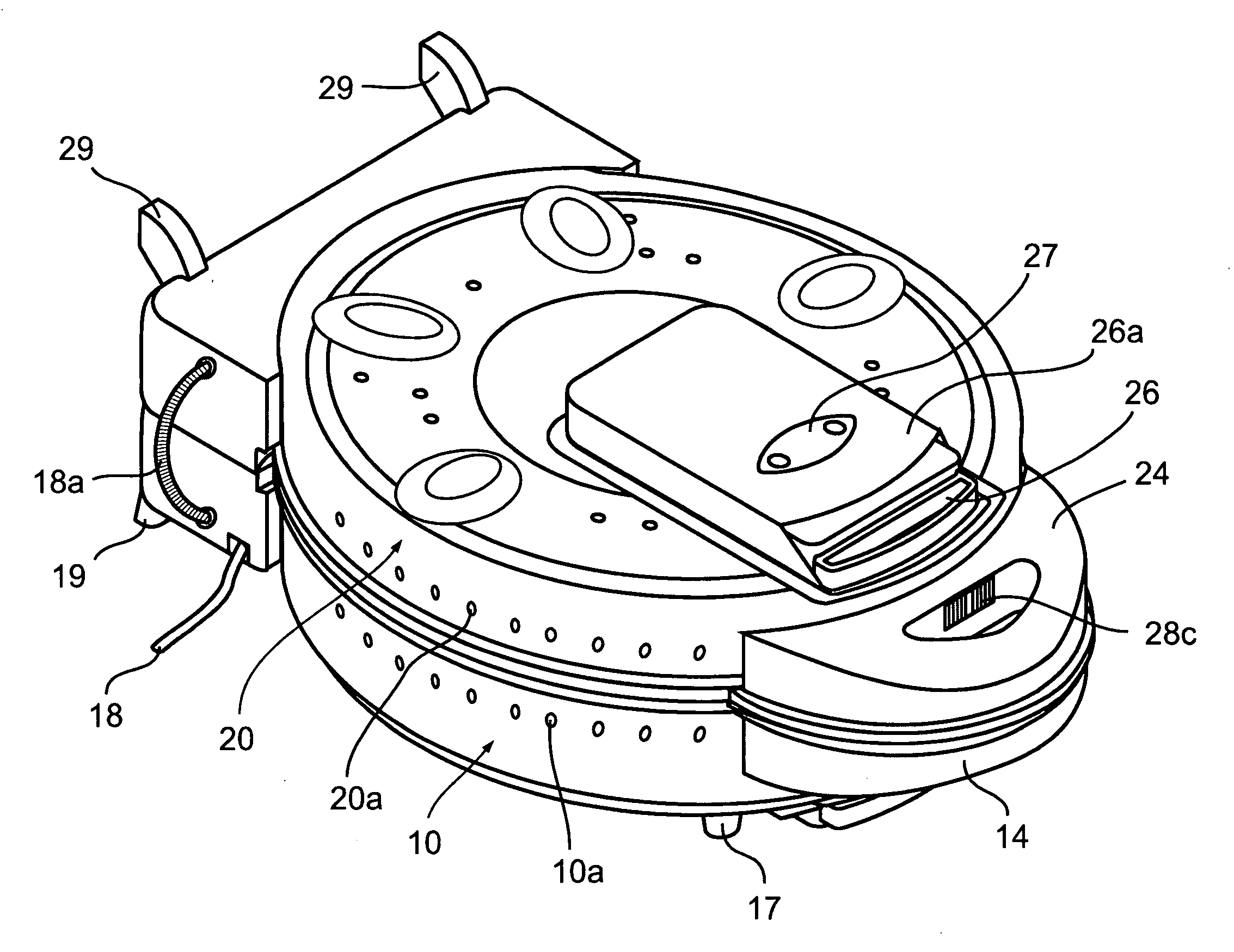
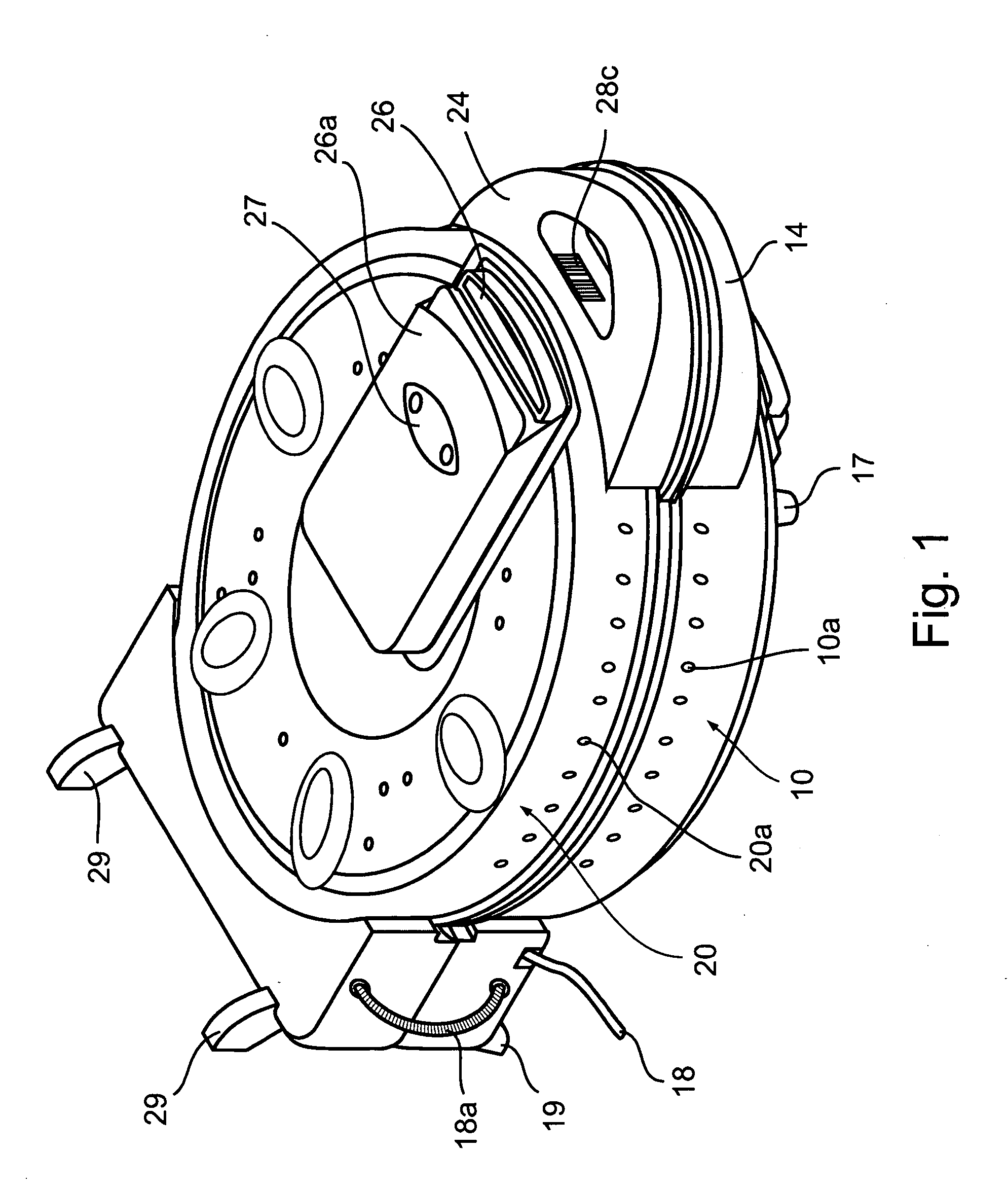
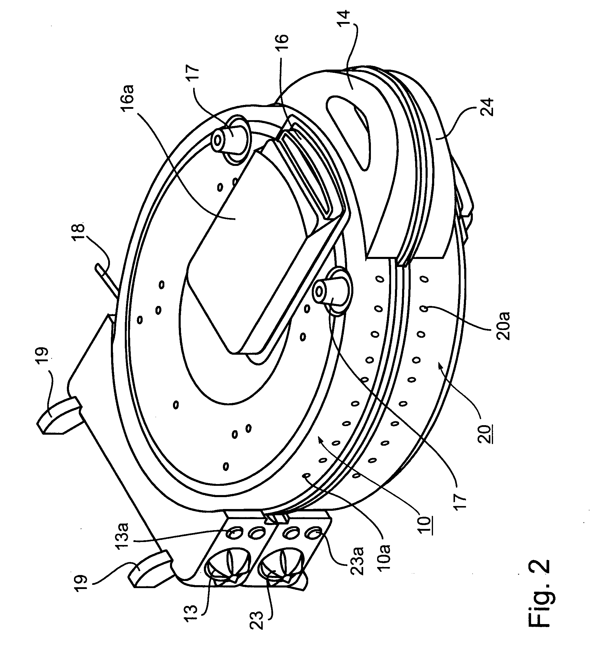
[0021]The cooking appliance illustrated in the drawings includes two cooking plates, generally designated 10 and 20, respectively, pivotally mounted to each other by a hinge assembly, generally designated 30 (FIG. 3) from an open position, as illustrated in FIG. 3, for permitting introduction and removal of food articles to be cooked, to a closed position, as illustrated in FIGS. 1, 2 and 6, for cooking the food article. Hinge assembly 30 is a slideable hinge of a known construction which permits the two cooking plates 10, 20, to be pivoted not only to an open position shown in FIG. 3, but also, to a selected closed position. The two possible closed positions permit the two cooking plates to be in either a close parallel relationship as shown in FIGS. 1 and 2, or to be spaced a distance from each other and maintain a parallel relationship, as shown in FIG. 6. For example, when the appliance is used for grilling steaks or hamburgers, preparing waffles, or the like, where the opposite...


PUM


Abstract

A cooking appliance including a pair of cooking plates pivotally mounted to each other by a slideable hinge at one end. Stops at their opposite ends are pre-settable to a first position permitting two-surface contact with the food article, or a second position supporting one cooking plate in spaced parallel relationship with respect to the other cooking plate to permit single-surface contact with the food article. At least one of the said cooking plates carries on its outer surface a removable tray communicating with the interior of the cooking appliance for receiving drippings accumulating within the cooking appliance during a cooking operation.

Description

RELATED APPLICATION[0001]This application is a continuation-in-part of U.S. Design patent application Ser. No. 29 / 253,822, filed Feb. 14, 2006, the contents of which are incorporated herein.FIELD AND BACKGROUND OF THE INVENTION[0002]The present inventions relates to cooking appliances, and particularly to cooking appliances which include pivotal cooking plates for cooking varied types of food articles, e.g., for grilling steaks, making waffles, warming buns, preparing pizzas, etc.[0003]Cooking appliances of the foregoing type generally include a pair of cooking plates pivotally mounted to each other from an open position for permitting the introduction and removal of the food articles to be cooked, to a closed position for cooking the food articles. In such cooking appliances, the pair of cooking plates are generally pivotally mounted to each other by a slideable hinge to permit the cooking plates to accommodate the food article between them during the cooking operation. Such cookin...

Claims


Application Information

Patent Timeline
IPC IPC(8): A47J37/06
CPCA47J37/0611A47J2037/0617A47J37/0871A47J37/0864
Inventor COHEN, ELIGRANT, ANN
Owner AAC TRADE LTD
Why Eureka
Try Eureka