Oil strainer structure of engine and oil return structure of engine

a technology of oil strainer and engine, which is applied in the direction of pressure lubrication, lubricant mounting/connection, lubrication elements, etc., can solve the problems of significant limitation in flexibility in positioning difficult to secure a sufficient area of the strainer, and difficult to arrange the oil suction hole, etc. achieve the effect of reliably performing gas-liquid separation, high flexibility, and enhancing flexibility in position determination

Inactive Publication Date: 2008-02-28
HONDA MOTOR CO LTD
View PDF19 Cites 8 Cited by
  • Summary
  • Abstract
  • Description
  • Claims
  • Application Information

AI Technical Summary

Benefits of technology

[0015] A second object of the invention is to minimize the number of components of the oil strainer and an oil return member, both of which are provided under the balancer housing.
[0033] With this structural arrangement, the oil return member is formed by joining together the upper member having the oil inlet hole leading to the oil return passage of the balancer housing and the lower member having the oil outlet hole opening in the oil in the oil pan. Therefore, it is possible to enhance the flexibility in determining the position of the oil outlet hole. Accordingly, the oil outlet hole can be arranged in a position where the oil outlet hole is less susceptible to the influence of the negative pressure generated by suction of the oil at the inlet hole of the oil strainer arranged inside the oil pan, thereby reliably performing gas-liquid separation between the blowby gas and the oil. Further, the lower member and the upper member, which are die-molded articles, are highly flexible in their shapes, whereby the oil outlet hole can be reliably arranged below the liquid surface of the of oil in the oil pan to prevent the pressure fluctuation in the crankcase from affecting the gas-liquid separation.

Problems solved by technology

However, in the oil strainer structure disclosed in Japanese Patent Application Laid-open No. 2001-74105, the oil strainer is integrally housed in the lower housing part of the balancer housing; and thus, the position of the oil strainer is limited to a space between the two balancer shafts, which causes the problems in that it is difficult to arrange the oil suction hole at an appropriate position, and it is difficult to secure a sufficient area of a strainer element of the oil strainer and a sufficient cross-sectional area of oil flow.
When the oil strainer and the oil return passage are integrally formed with the balancer housing, a significant limitation is imposed on flexibility in positioning of the oil suction hole of the oil strainer and positioning of the oil outlet hole of the oil return passage.
Also, when waves are formed on the liquid surface of the oil in the oil pan due to acceleration, deceleration or turn of the vehicle, air is mixed in the oil suctioned through the oil strainer, leading to a possibility that the oil pump does not normally operates.
Thus, in the conventional structural arrangements, a baffle plate is provided inside the oil pan to suppress the formation of waves on the liquid surface of the oil, but this increases the number of components.
Therefore, a negative pressure is generated by suction of the oil pump in the vicinity of the oil suction hole of the oil strainer, and the negative pressure affects the oil outlet hole of the oil return passage, which may adversely affect the separation of the oil from the blowby gas in the gas-liquid separating chamber.
In order to eliminate this drawback, it is desirable that the oil outlet hole of the oil return passage is positioned away from the oil suction hole of the oil strainer, but it is difficult to freely select the position of the oil outlet hole because the oil outlet hole opens directly in the lower surface of the balancer housing.

Method used


Image

  • Oil strainer structure of engine and oil return structure of engine
  • Oil strainer structure of engine and oil return structure of engine
  • Oil strainer structure of engine and oil return structure of engine

Examples


first embodiment

[0046] the present invention will be described with reference to FIGS. 1 to 9.

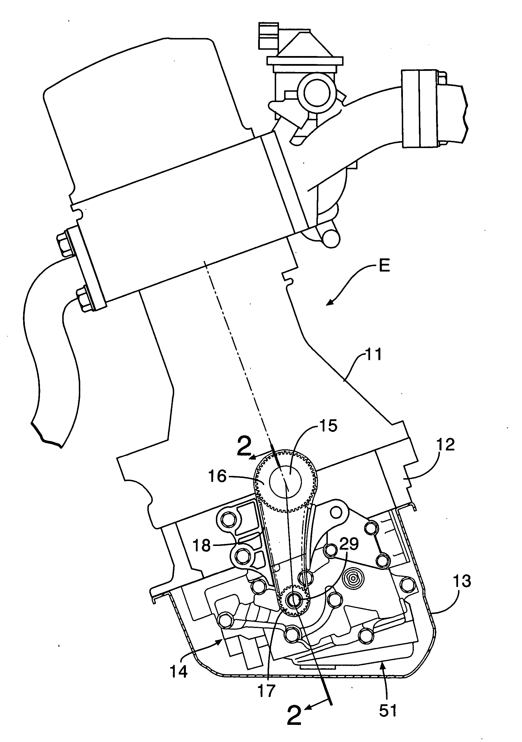
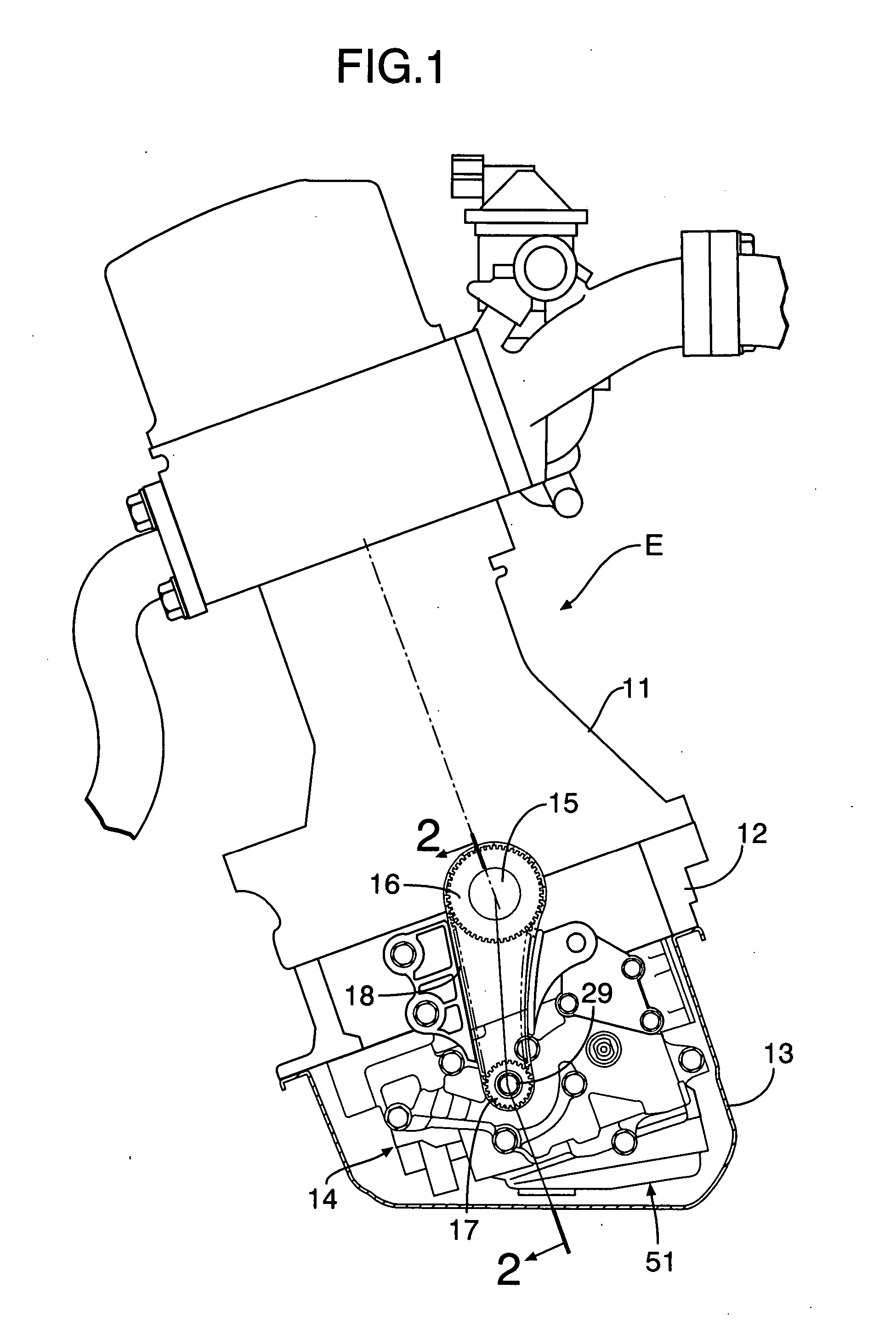
[0047]FIGS. 1 and 2 show the following structural arrangement. A lower block 12 is fixed to a lower surface of a cylinder block 11 of a diesel engine E of an automobile. An oil pan 13 is fixed to the lower surface of the lower block 12. Provided on a lower surface of the lower block 12 is a balancer device 14 which reduces secondary vibration of the engine E, and which is housed in the oil pan 13. A crankshaft 15 is rotatably supported between the cylinder block 11 and the lower block 12. A drive sprocket 16 is provided at an end of the crankshaft 15. A driven sprocket 17 is provided at an end of a drive balancer-shaft 29 of the balancer device 14. An endless chain 18 is wound around the drive and driven sprockets 16 and 17.

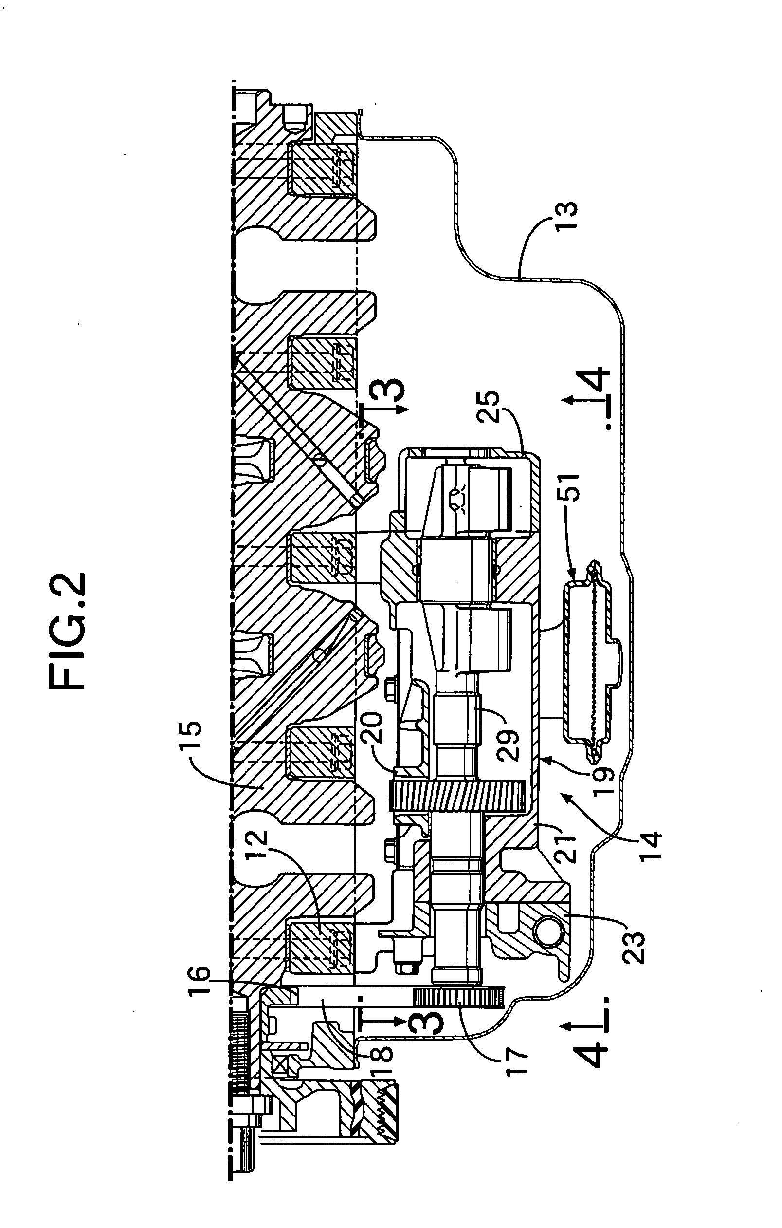
[0048] FIGS. 3 to 6 show the following structural arrangement. The balancer device 14 has a balancer housing 19 including an upper housing part 20 and a lower housing part 21. The uppe...


PUM


Abstract

An oil strainer includes: a lower member having an oil suction hole opening in oil stored in an oil pan; an upper member having an oil discharge hole leading to an oil pump; and a strainer element. The lower member and the upper member are joined to each other with the strainer element held between joint surfaces of the upper and lower members. Thus, it is possible to form the oil strainer into a flat shape so as to be compactly arranged in a narrow space, and also maximize an area of the strainer element to prevent clogging. Further, the lower member and the upper member, which are die-molded articles, are highly flexible in their shapes, whereby the oil suction hole and the oil discharge hole can be arranged in the most suitable positions, and the cross-sectional area of oil flow can be sufficiently secured.

Description

RELATED APPLICATION DATA [0001] The Japanese priority application Nos. 2006-230199, 2006-230200, 2006-230201 and 2006-230202 upon which the present application is based are incorporated in their entirety herein by reference. BACKGROUND OF THE INVENTION [0002] 1. Field of the Invention [0003] The present invention generally relates to an oil strainer structure of an engine, which includes an oil strainer for filtering oil in an oil pan, the oil strainer being arranged between a balancer housing and the oil pan of the engine and supported by the balancer housing. [0004] Also, the present invention generally relates to an oil return structure of an engine, which includes an oil return member for returning oil separated from blowby gas to an oil pan, the oil return member being arranged between a balancer housing and the oil pan of the engine. [0005] 2. Description of the Related Art [0006] Japanese Patent Application Laid-open No. 2001-74105 discloses an oil strainer structure of an en...

Claims


Application Information

Patent Timeline
Patent Type & Authority Applications(United States)
IPC IPC(8): F01M11/00
CPCF01M2011/007F01M11/0004
Inventor KOYAMA, YOSHIAKI
Owner HONDA MOTOR CO LTD
Why Eureka
Try Eureka