Gas sensor arrangement with reduced settling time

a gas sensor and settling time technology, applied in the field of gas sensor arrangement, can solve the problems of considerable amount of gas escaping unnoticed, the settling time or period until usable measurement results are available, and the first 10-15 measurement values are not usable, so as to achieve the effect of reducing the settling time increasing the reliability of the gas sensor arrangemen

Active Publication Date: 2006-01-19
BAYERISCHE MOTOREN WERKE AG
View PDF9 Cites 7 Cited by
  • Summary
  • Abstract
  • Description
  • Claims
  • Application Information

AI Technical Summary

Benefits of technology

[0012] It is therefore an object of the invention to provide a gas sensor arrangement where the settling time of the gas sensor arrangement is reduced, and the reliability of the gas sensor arrangement is increased.

Problems solved by technology

These types of gas sensor arrangements have a crucial disadvantage in that when the measuring radiation source is switched-on, the settling time or period until usable measurement results are available is relatively long, because only a relatively small amount of energy is radiated per pulse.
Thus, the first 10-15 measurement values are not usable.
This is particularly problematic in safety applications, where the gas sensor arrangement has to be frequently switched-on and off.
As a result, a considerable amount of gas could escape unnoticed through a gas leak during the referencing phase.

Method used


Image

  • Gas sensor arrangement with reduced settling time
  • Gas sensor arrangement with reduced settling time
  • Gas sensor arrangement with reduced settling time

Examples


first embodiment

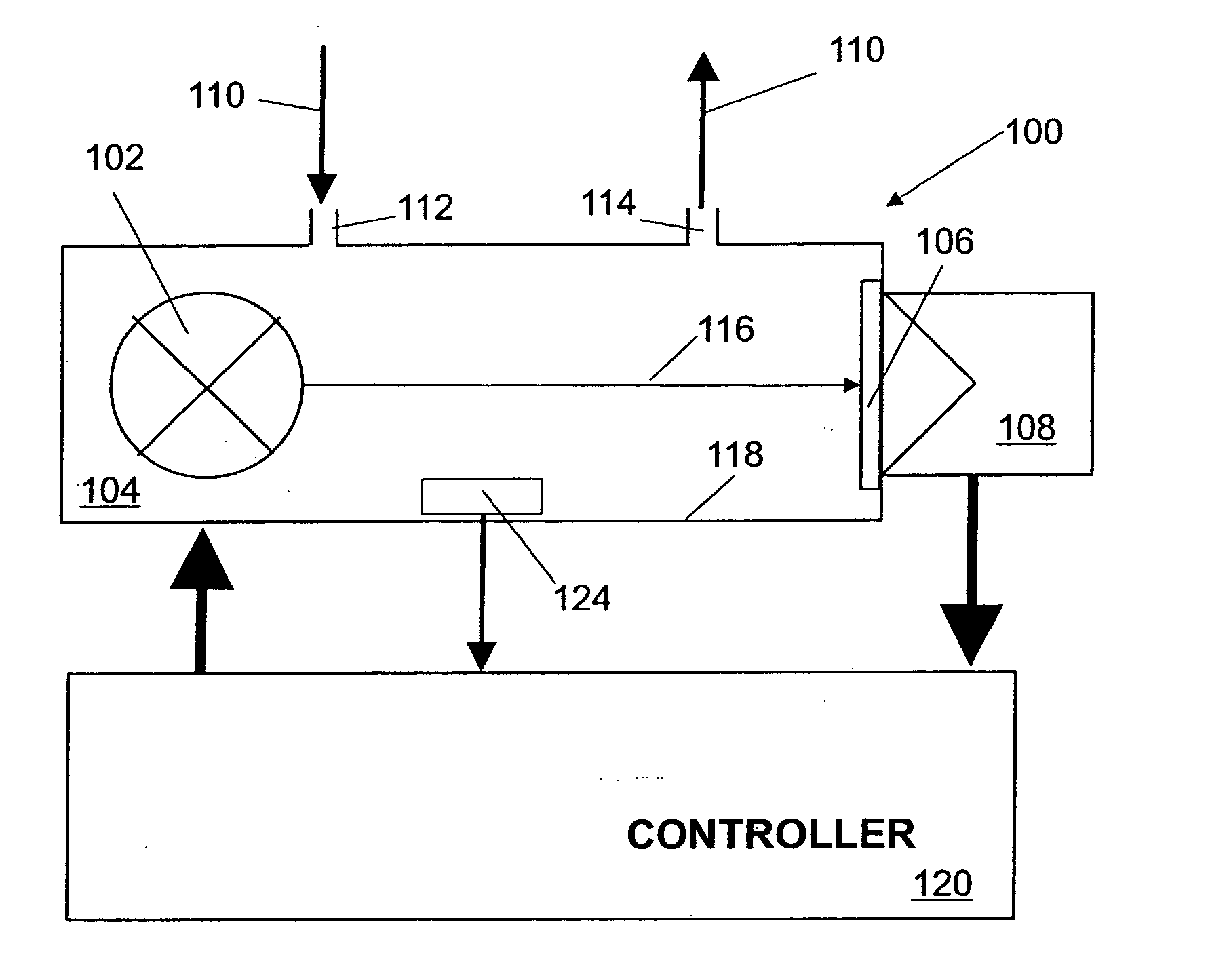
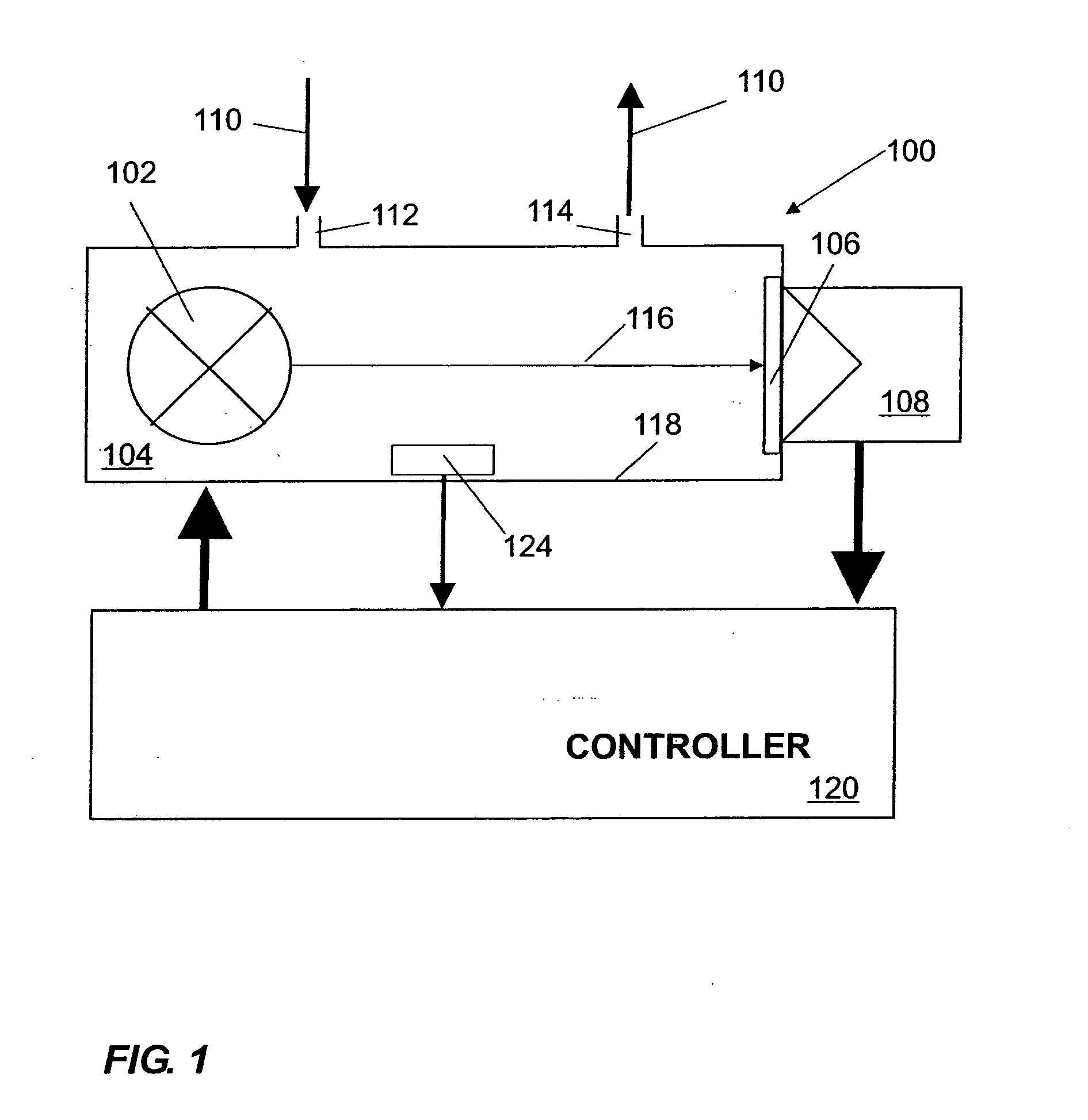
[0023]FIG. 1 shows a gas sensor arrangement 100 according to the invention. As shown in FIG. 1, the gas sensor arrangement 100 comprises a measuring radiation source 102, a gas measuring chamber 104, an optical wavelength filter 106, and a radiation detector 108. The gas sensor arrangement 100 may be, for example, a non-dispersive infrared (NDIR) sensor where the measuring radiation source 102 is a broadband infrared radiation source and the radiation detector 108 detects infrared radiation.

[0024] The gas measuring chamber 104 includes an inlet 112 and an outlet 114. A measuring gas 110 is pumped into the gas measuring chamber 104 through the inlet 112 or diffused therein. The measuring gas 110 contains at least one analyte. The concentration of the measuring gas 110 can be determined electro-optically via the absorption of a specific wavelength in the infrared range. A temperature sensor 124 may be provided to detect the temperature in the gas measuring chamber 104.

[0025] Radiatio...

second embodiment

[0028]FIG. 6 shows a gas sensor arrangement 100 according to the invention. The gas sensor arrangement 100 comprises a measuring radiation source 102 and a reference radiation source 103. The measuring and reference radiation sources 102, 103 are arranged such that a length of the paths of the radiation 116, 117 from the measuring and reference radiation sources 102, 103, respectively, to a radiation detector 108 is the same or that the measuring and reference radiation sources 102, 103 are positioned symmetrically to an axis of symmetry of a gas measuring chamber 104. As shown in FIG. 9, the controller 120 comprises a timing control 126 and a signal processing unit 128. A temperature monitoring unit and / or a timer can also be provided in order to establish the time of the respective switching from the warming-up to the measuring operation and vice versa.

[0029] The reference radiation source 103 is periodically switched-on to monitor the aging state of the measuring radiation source...


PUM

PropertyMeasurementUnit
wavelengthaaaaaaaaaa
concentrationaaaaaaaaaa
frequencyaaaaaaaaaa

Abstract

A gas sensor arrangement for detecting the presence or concentration of an analyte in a measuring gas comprises a gas measuring chamber having an inlet for receiving the measuring gas. A measuring radiation source is arranged in the gas measuring chamber. The measuring radiation source emits radiation in a non-uniform pulse sequence according to a signal from a controller. A radiation detector receives the radiation emitted from the measuring radiation source. The radiation detector sends an output signal to the controller for processing.

Description

FIELD OF THE INVENTION [0001] The invention relates to a gas sensor arrangement comprising at least a measuring radiation source, a gas measuring chamber, and a radiation detector wherein the radiation detector generates an output signal dependant on the presence and / or concentration of an analyte in a measuring gas in the gas measuring chamber. BACKGROUND OF THE INVENTION [0002] Gas sensor arrangements for detecting a wide variety of analytes, for example methane or carbon dioxide, are well known. Examples of such gas sensors are disclosed in EP 0 616 207 A2, WO 00 / 55603 A1, and DE 199 251 96 C2. The gas sensors comprise a measuring radiation source, a gas measuring chamber, and a radiation detector. The gas sensors are based on the principle that a large number of polyatomic gases absorb radiation, particularly in an infrared wavelength range. The absorption occurs at a wavelength characteristic for the gas, for example at 4.24 μm for carbon dioxide. Using gas sensors, it is there...

Claims


Application Information

Patent Timeline
Patent Type & Authority Applications(United States)
IPC IPC(8): G01J5/02G01N21/31G01N21/35G01N21/61
CPCG01N21/3151G01N21/61G01N21/3504
Inventor MINUTH, RUDIFISCHER, JOERGTILLE, THOMAS
Owner BAYERISCHE MOTOREN WERKE AG
Why Eureka
Try Eureka