Oil filter assembly

a technology of oil filter and oil module, which is applied in the direction of filtration separation, membrane technology, separation process, etc., can solve the problems of reducing the filtering ability, prone to sticking, and the entire filter assembly must be replaced, so as to facilitate the removal of the oil filter module from the adapter

Inactive Publication Date: 2007-08-16
WEINBERGER KEITH R +3
View PDF48 Cites 29 Cited by
  • Summary
  • Abstract
  • Description
  • Claims
  • Application Information

AI Technical Summary

Benefits of technology

[0015] Certain embodiments of the present invention also provide a method of disconnecting an oil filter module from an adapter secured to a mounting stud of an engine. The method may include: (i) rotating the oil filter module relative to the adapter, wherein the rotating comprises rotating a module actuation member fixed within the filter module; (ii) causing an adapter actuation member movably secured within the adapter and mated to the module actuation member to rotate in response to the rotating the oil filter module step, (iii) moving the adapter actuation member into contact with a detent that is retained by a notch to secure the filter module to the adapter, (iv) disengaging the detent from the notch through the moving the adapter actuation member step, and (v) disconnecting the oil filter module from the adapter through the disengaging step, wherein the disconnecting step comprises removing the module actuation member from a mating position with the adapter actuation member. Removal of the oil filter module from the adapter may be facilitated by spring action.

Problems solved by technology

Eventually, an oil filter assembly, or at least the filtering medium within the assembly, needs to be replaced due to the fact that it becomes clogged with numerous impurities, thereby diminishing its filtering ability.
When the filter medium is clogged, the entire filter assembly must be replaced.
The threads of, and / or other components (such as gaskets) located proximate to such threadable interfaces, are prone to sticking, which can pose difficulties in removing an oil filter from the engine (for a one-part filter assembly), or the casing from the base (for a two- or three-part filter assembly).
In many vehicles, however, the oil filter assembly is located at a position that is difficult to access.
Thus, using a tool with some oil filters may be difficult.

Method used


Image

  • Oil filter assembly
  • Oil filter assembly
  • Oil filter assembly

Examples


Embodiment Construction

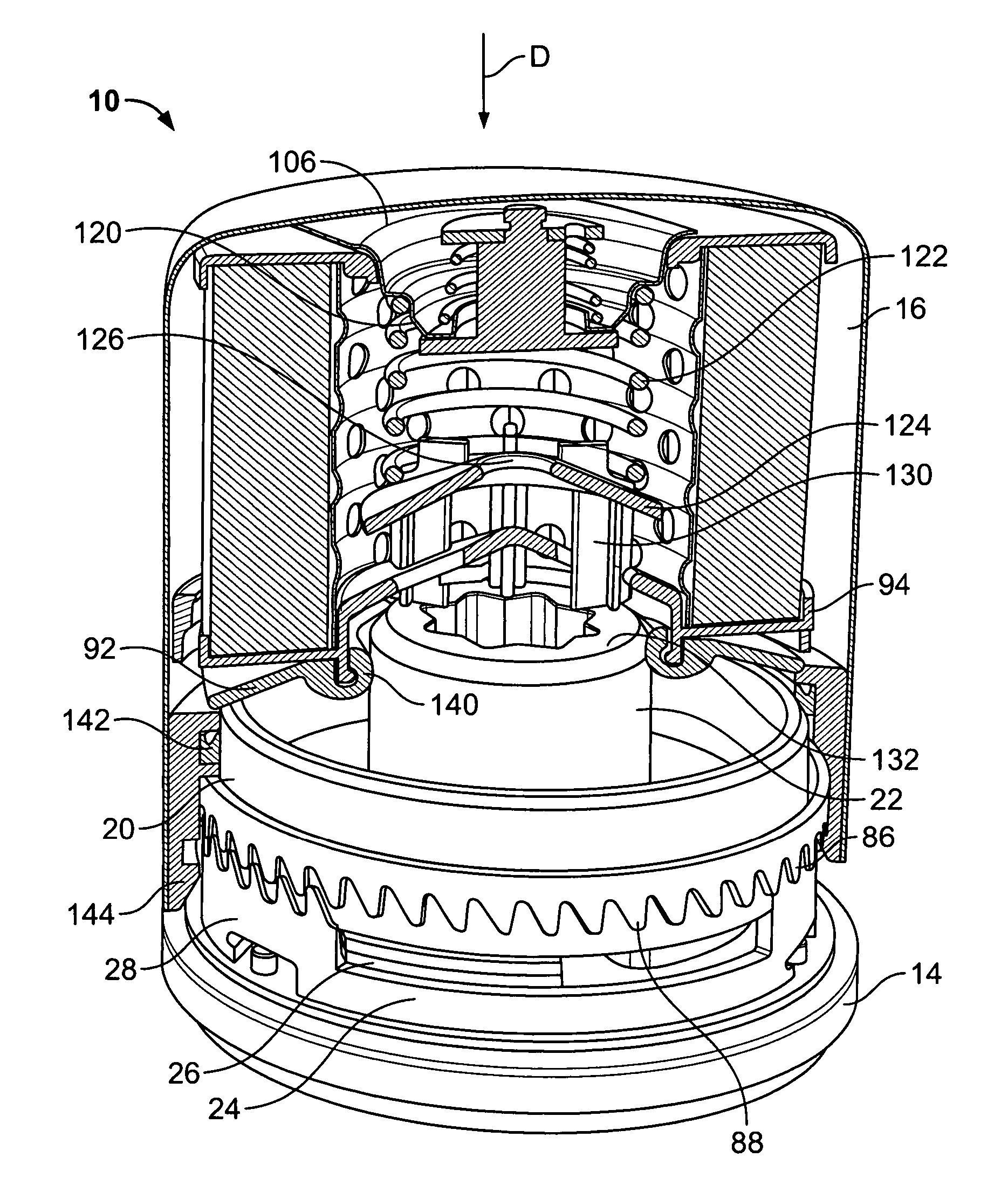
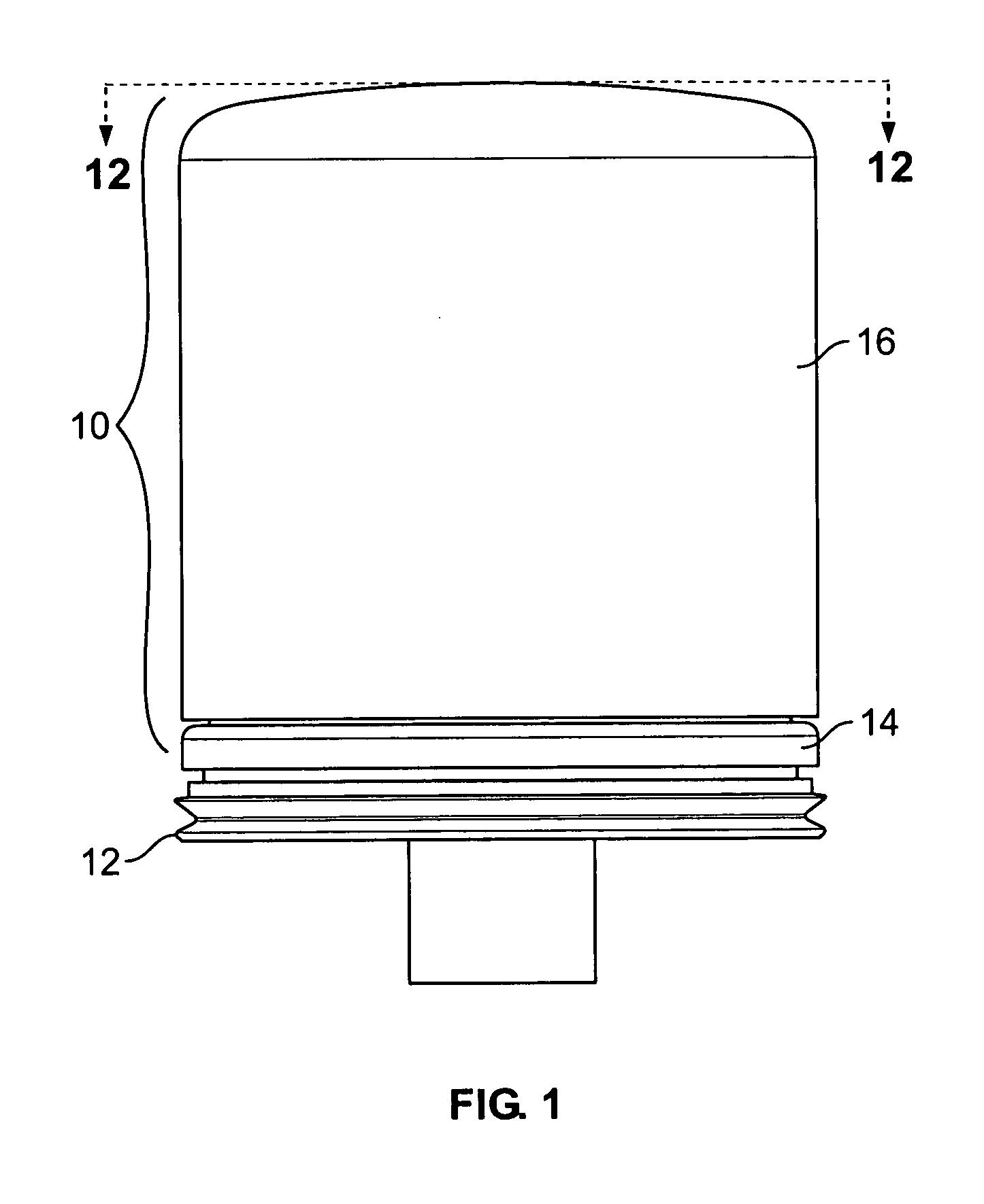
[0032]FIG. 1 illustrates a front view of a fluid filter assembly 10 secured to a mounting stud 12 of an engine according to an embodiment of the present invention. The fluid filter assembly 10 includes a first segment, such as a base or adapter 14 and a second segment, such as a filter refill, insert or module 16. The filter assembly 10 is configured to filter fluid, such as oil within an internal combustion engine. The filter assembly 10 is a two piece assembly in which the adapter 14 is configured to threadably secure to the mounting stud 12, while the filter module 16 is configured to be threadably or otherwise removably secured to the adapter 14, as discussed below.

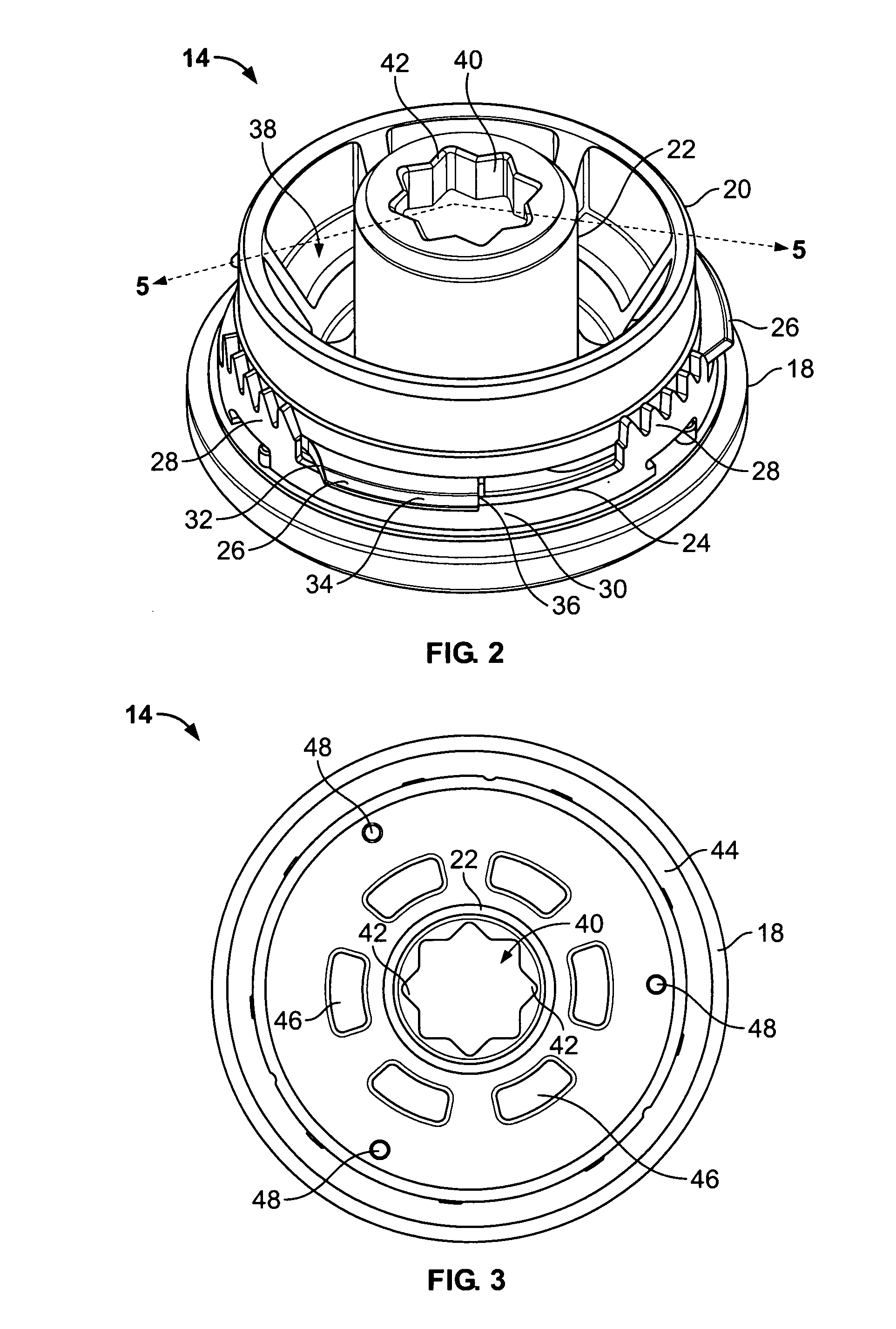
[0033]FIG. 2 illustrates an isometric top view of the adapter 14. The adapter 14 may be a metal, such as steel, an aluminum silicon alloy, or a nonmetallic material, and includes a generally circular base 18 integrally formed with an outer wall 20 and a fluid outlet tube 22. The base 18 supports a lower actuation rin...


PUM

PropertyMeasurementUnit
forceaaaaaaaaaa
shapeaaaaaaaaaa
reciprocal structuresaaaaaaaaaa

Abstract

A fluid filter system includes a first segment and a second segment. The first segment includes a filter medium, a notch adapted to engage a detent, and a first actuation member. The second segment includes a detent engageable with the notch to secure the first segment to the second segment, and a second actuation member. The detent is moveable between a locked position and an unlocked position, and is normally biased into the locked position. The second actuation member is configured to cooperate with the first actuation member in order to move the detent between the locked and unlocked positions.

Description

BACKGROUND OF THE INVENTION [0001] Embodiments of the present invention generally relate to a fluid filter assembly, such as an oil filter assembly, and more particularly to a fluid filter assembly that is configured to be quickly and easily changed. [0002] A conventional oil filter assembly for an internal combustion engine typically includes a threaded end, which is rotated, twisted, or spun, onto a corresponding mounting structure of the engine. Once the assembly is mounted onto the engine, oil is circulated through the engine for filtering. Unfiltered oil from the engine is passed through a filtering medium, such as a pleated paper cylinder, of the assembly. As the unfiltered oil passes through the filtering medium, impurities contained within the oil are retained by the filter medium. Filtered oil is then passed back into the engine. Eventually, an oil filter assembly, or at least the filtering medium within the assembly, needs to be replaced due to the fact that it becomes clo...

Claims


Application Information

Patent Timeline
Patent Type & Authority Applications(United States)
IPC IPC(8): B01D27/00
CPCB01D27/08B01D35/147B01D2201/4076B01D27/103B01D27/106B01D35/153B01D35/306
Inventor WEINBERGER, KEITH R.JOHNSON, ALAN B.TURCHI, MARIO A.JOACHIM, ROBERT
Owner WEINBERGER KEITH R
Why Eureka
Try Eureka