Switch and recording medium

Inactive Publication Date: 2007-08-16
SONY CORP
View PDF9 Cites 22 Cited by
  • Summary
  • Abstract
  • Description
  • Claims
  • Application Information

AI Technical Summary

Benefits of technology

[0015] According to an embodiment of the invention, an operation portion is separated from the detection portion as well as the operation portion has a magnet while the detection portion has the magnetic-field-sensing element. The detection portion also has the attraction member, which generates a magnetically attracting force between the detection portion and the operation portion. When the operation portion is operated with the operation portion being attracted by the attraction member to the detection portion, a position of the magnet alters against the magnetic-field-sensing element in response to the operation which is applied to the operation portion so that the detection portion can generate the switching signal based on the output of the magnetic-field-sensing element in response to an operation which is applied to the operation portion.
[0016] Thus, even when the detection portion is enclosed in a perfectly sealed casing a

Problems solved by technology

When, however, the switches shown in FIGS. 1 and 2 are used as write-protection switch in the recording medium of non-contact type, it is difficult

Method used


Image

  • Switch and recording medium
  • Switch and recording medium
  • Switch and recording medium

Examples


Example

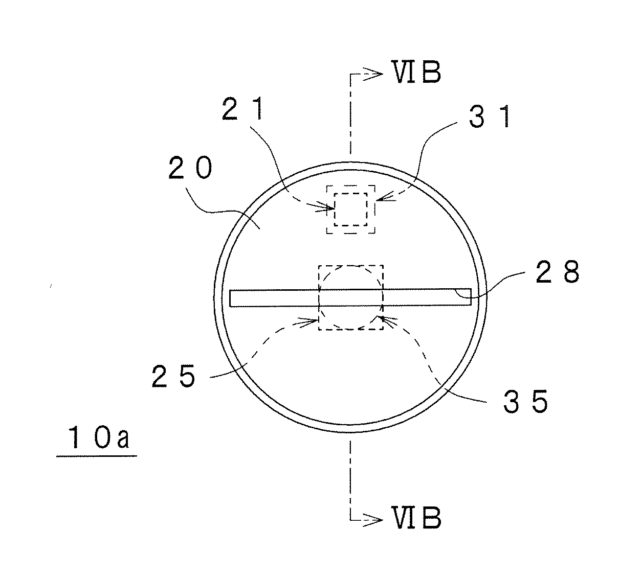
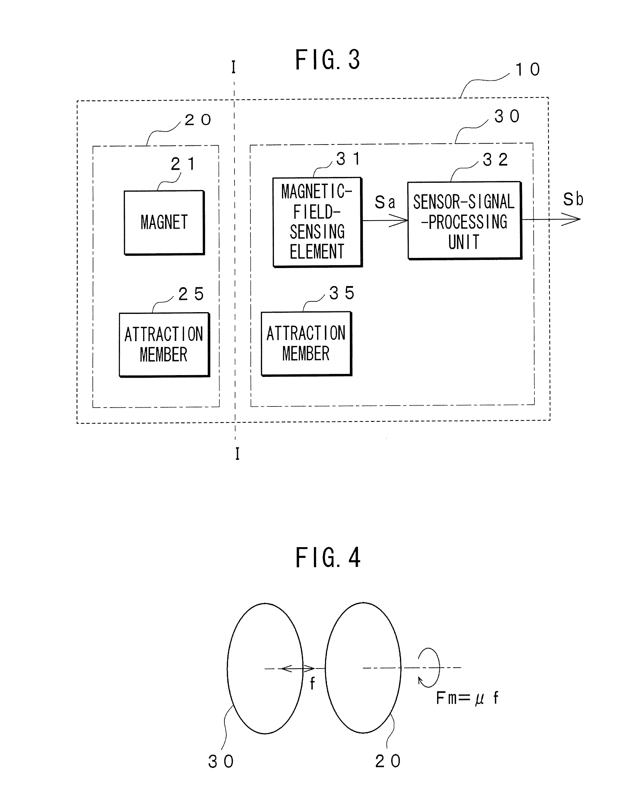
[0029] The following will describe embodiments of the present invention with reference to the accompanied drawings. FIG. 3 shows a basic configuration of an embodiment of a contactless switch 10 according to the invention. The contactless switch 10 has an operation portion 20 that a user operates and a detection portion 30 that detects an operation by the user, which is applied to the operation portion 20. The operation portion 20 and the detection portion 30 may be physically separated from each other in the contactless switch 10 at a position thereof along lines I-I shown in FIG. 3. When this contactless switch 10 is enclosed in any equipment having, for example, a sealed structure and is used for switching therefor, the operation portion 20 is provided out of the sealed equipment and the detection portion 30 is enclosed in the sealed equipment. The operation portion 20 contains a magnet 21 and the detection portion 30 contains a magnetic-field-sensing element 31. Thus, when the u...


PUM


Abstract

A switch has a detection portion that contains a magnetic-field-sensing element and an attraction member. The attraction member generates a magnetically attracting force. The detection portion generates a switching signal based on an output of the magnetic-field-sensing element.

Description

CROSSREFERENCE TO RELATED APPLICATION [0001] The present invention contains subject matters related to Japanese Patent Application JP 2006-034262 filed in the Japanese Patent Office on Feb. 10, 2006, the entire contents of which being incorporated herein by reference. BACKGROUND OF THE INVENTION [0002] 1. Field of the Invention [0003] The present invention relates to a switch and a recording medium such as an integrated circuit (IC) card using the same. [0004] 2. Description of Related Art [0005] A switch 100, shown in FIG. 1, that is used in electronic equipment or the like has switched an electric circuit on or off by moving a movable contact 111 provided in an operation portion 110 of the switch 100 backwards and forwards or stirring it based on any switching operations by a user to establish contact or non-contact condition of the movable contact 111 with a fixed contact 121 of a detection portion 120 of the switch 100. [0006] In a switch wherein the movable contact 111 has been...

Claims


Application Information

Patent Timeline
IPC IPC(8): H01H37/00
CPCH01H36/0066
Inventor NAKASUJI, MASAKISAWAI, JUNOYA, NOBORUIKEYAMA, CHIAKISHIMOSATO, TSUTOMU
Owner SONY CORP
Why Eureka
Try Eureka