MEMS device and method

US20070188847A1Inactive Publication Date: 2007-08-16TEXAS INSTR INC

Image

  • MEMS device and method
  • MEMS device and method
  • MEMS device and method

Examples


Embodiment Construction

[0032] Presently preferred embodiments of the present invention and their implementation are discussed in detail below. It should be appreciated, however, that the present invention provides many applicable inventive concepts that can be embodied in a wide variety of specific contexts. The specific embodiments discussed are merely illustrative of specific ways to make use of the invention, and do not limit the scope of the invention.

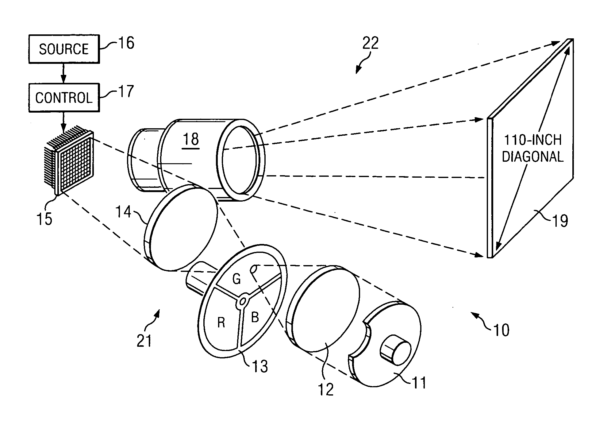
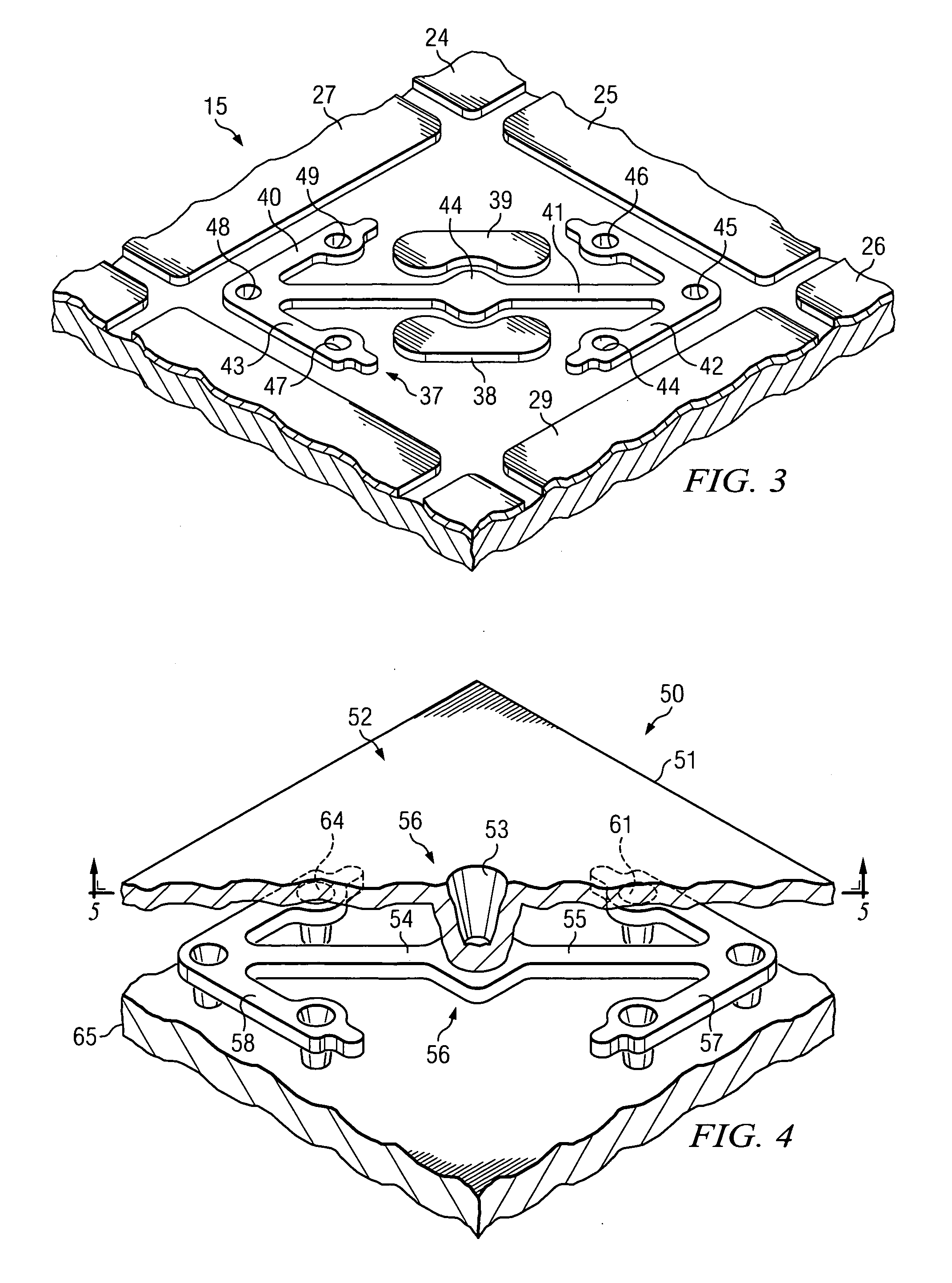
[0033] The present invention will be described with respect to preferred embodiments in a specific context, namely a micro-mirror hinge assembly for a DMD (digital micro-mirror device) for use in a projection display system. The invention may also be applied, however, in other MEMS applications as well, for example in laser printers.

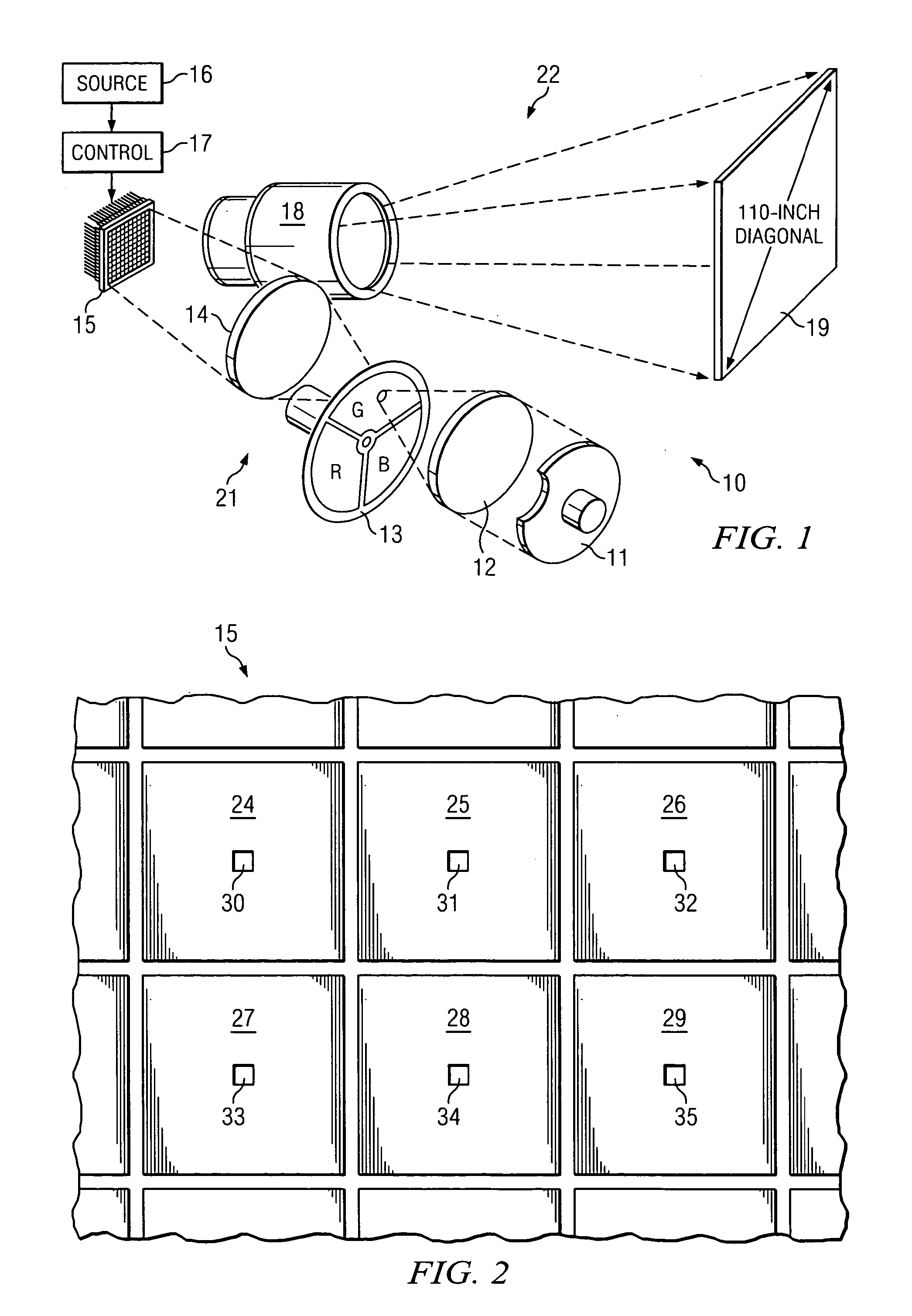
[0034] As described above, applications such as DLP® projection display systems employ a spatial light modulator (SLM) such as a DMD. The ability of the DMD to modulate light in such a system depends largely on the movement...


PUM


Abstract

A micro-mirror hinge assembly for use in a MEMS device such as a DMD, and method. In a preferred embodiment, a first hinge member is mounted to a substrate by one or more via structures that may be integrally-formed with the hinge-member to facilitate torsional deformation. A second hinge member also configured for torsional deformation is mounted to and usually above the first hinge member so that deformation of the second hinge member occasions deformation of the first. Additional hinge members, each mounted to at least one other hinge member, may also be present. A mirror or similar reflecting surface is mounted to the second hinge member at one or more mirror vias. The MEMS device may include means for selectively inducing mirror reorientation, which in turn causes deformation in the hinge members of the hinge assembly.

Description

TECHNICAL FIELD [0001] The present invention relates generally to the field of MEMS applications, such as projection display systems and laser copiers, and more particularly to a DMD using a stacked-hinge configuration. BACKGROUND [0002] MEMS, or micro electromechanical systems, are used, for example, to create an image in popular electronic products such as projection displays and laser printers. In these exemplary applications, the MEMS component modulates light received from a light source and traveling along an optical path, altering the characteristics of the light beam to produce an image. (For this reason, a MEMS of this type may be called an ‘optical’ MEMS, initialized ‘MOEMS’.) A projection display, for example, may be used for displaying a visual image for viewers of a high-definition television (HDTV). One such projection display system is marketed in connection with the name Digital Light Processing®, or DLP®, available from Texas Instruments Incorporated of Dallas, Tex....

Claims


Application Information

Patent Timeline
16 Aug 2007
Publication
US20070188847A1
IPC
G02B26/00
CPC
G02B26/0841; G02B26/0833
Inventors
MCDONALD, WILLIAM CRAIG; GONZALEZ, ARMANDO