Machine vision counting system apparatus and method

a technology of machine vision and counting system, applied in the field of counting system, can solve the problems of reducing performance, reducing accuracy, and comparatively slow process

Inactive Publication Date: 2007-08-16
ILLINOIS TOOL WORKS INC
View PDF29 Cites 88 Cited by
  • Summary
  • Abstract
  • Description
  • Claims
  • Application Information

AI Technical Summary

Benefits of technology

[0012] In accordance with yet another embodiment of the present invention, a machine-vision-based counting system is presented. The counting system includes a counter system control function, a stage illumination function whereby the units to be counted by the system are lighted, a stage image acquisition function under the direction of the control function, using the illumination function lighting to acquire an image, a counter system unit geometry access function, wherein unit shape information is provided in a form usable within the counter, a unit discrimination function, whereby an individual unit within the image is identified in accordance with unit shape information, a unit count function, wherein an individual unit within the image is counted and the image managed to allow further discrimination and count operations, a unit count reporting function, wherein a numerical value for

Problems solved by technology

This procedure is comparatively slow, and can be cumbersome.
Such devices can have reduced performance due to sample-to-sample or batch-to-batch piece weight variations, which can cause absolute count errors.
Such devices may be insensitive to such errors as sample-to-sample or batch-to-batch weight variations, and may detect some types of unit defects, ignore small fragments, or otherwise in

Method used


Image

  • Machine vision counting system apparatus and method
  • Machine vision counting system apparatus and method
  • Machine vision counting system apparatus and method

Examples


first embodiment

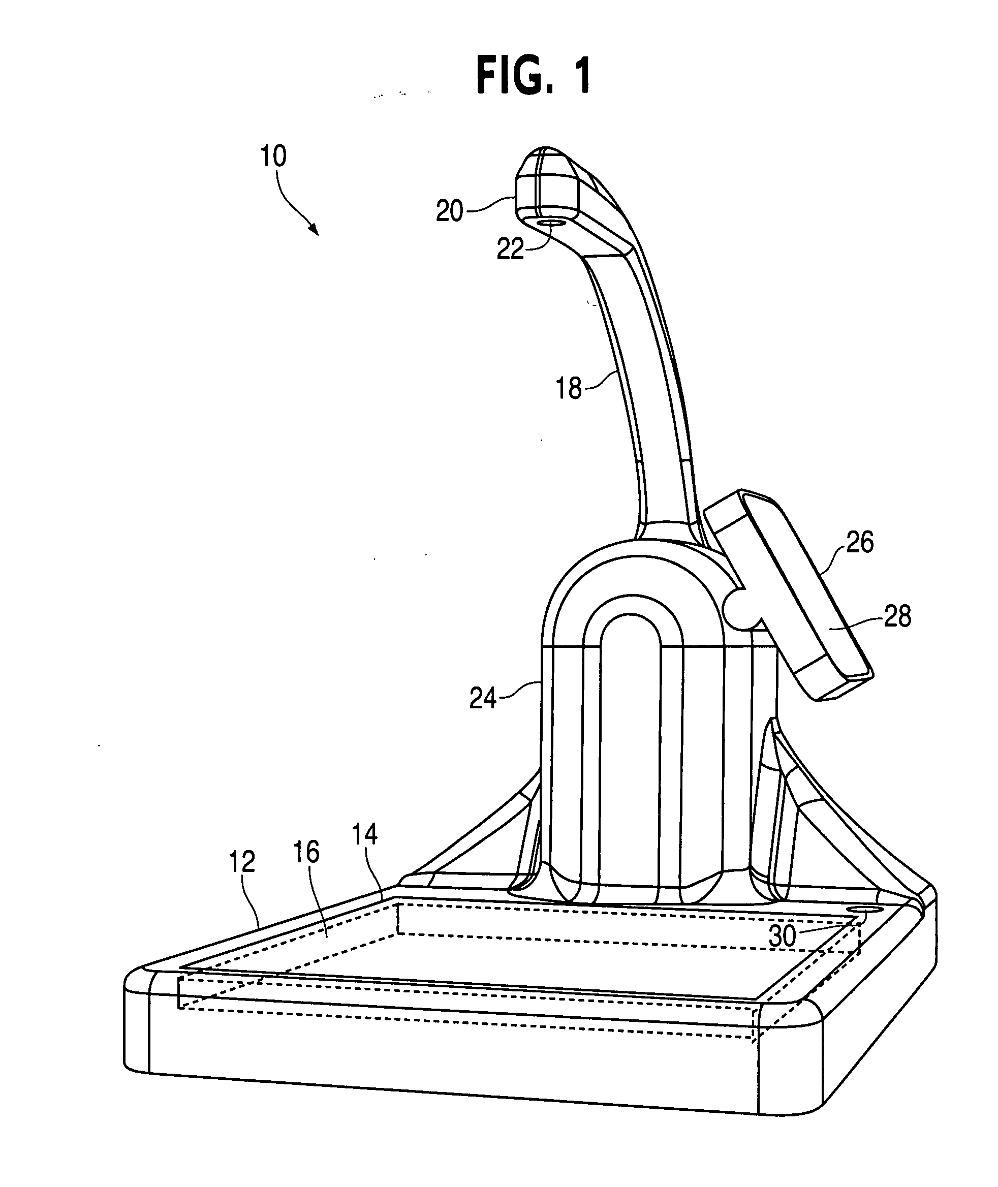
[0045]FIG. 1 shows a counter 10, having a base 12 for placement of the counter 10 on a surface. The counter 10 includes a stage 14 for positioning of units to be counted, an illuminator 16 oriented to provide illumination upward from the upper surface of the stage 14, and a neck 18, extending upward from the vicinity of the stage 14, that positions an imager head 20. The imager head 20 affixes and directs an image acquisition component (imager) 22 toward the stage 14, permitting the imager 22 to acquire an image of any materials placed on the stage 14 and backlit by the illuminator 16. A circuit housing 24, configured to enclose electronic circuitry for operation of the counter 10, is, in the embodiment shown, at least partially integrated into the structure of the counter 10. An operator interface cluster 26, configured to provide display and input for a user, is likewise integrated at least in part into the structure of the counter 10. The operator interface cluster 26 includes a ...

second embodiment

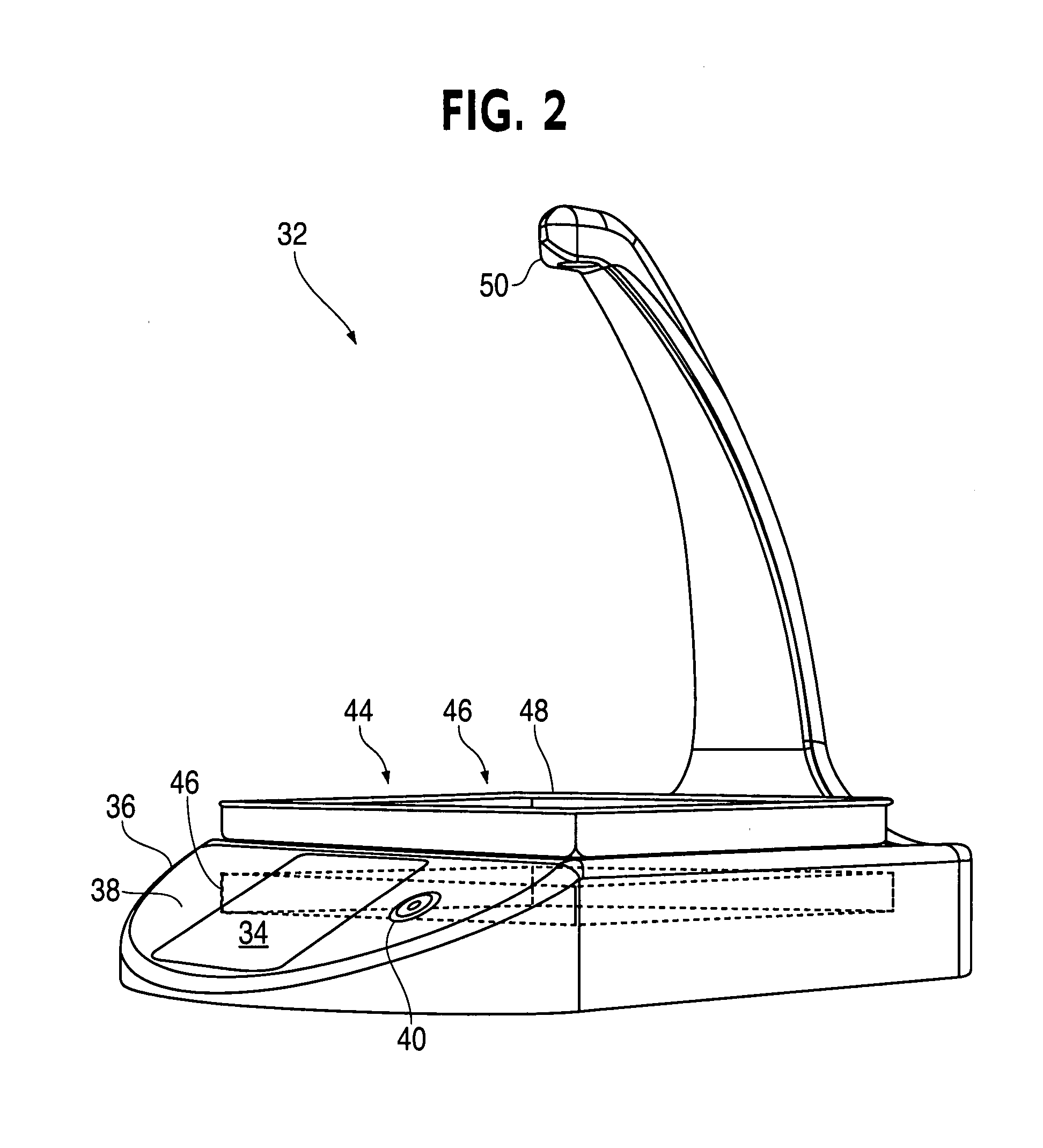
[0046]FIG. 2 shows a counter 32. This embodiment differs from the embodiment of FIG. 1 in having an operator interface cluster 34 integrated into a base 36 on a sloped face 38 thereof, while a power switch 40 is located adjacent to the operator interface cluster 34. Electronic components for controlling the counter 32 are located within the base 36, beneath a stage 44 and an illuminator 46, rather than in a housing 24 integrated in part into the neck 18 as shown in FIG. 1. Shown in this embodiment is a user-supplied and user-removable tray 48, which tray 48 may be washable, sterilizable, and / or disposable, and which is substantially transparent over at least a floor area thereof—that is, a bottom surface surrounded at least in part by walls—to such portion of the electromagnetic spectrum as is used for illumination. Such a tray 48 may be smaller in extent than the illuminator 46 in at least some embodiments, which may tend to prevent units from resting thereon without being detectab...

embodiment 114

[0059]FIG. 5 is an example of another embodiment 114, wherein a source 116 is positioned substantially at the level of the camera 118, for example. Such a source 116 may be diffuse, that is, may have largely uniform and low energy density emission over a relatively broad surface, or may approximate a point source, that is, may emit with comparatively high energy density from a small spot. Each such configuration, as well as intermediate forms such as multiple discrete spot sources, may be superior in conjunction with particular imaging methods.

[0060] For some embodiments, a passive reflector 120 beneath the stage 122, which may be focused, can be used to reflect light from the source 116 back to the camera 118, with deflection or diffusion of the light by the units 124 providing contrast. The reflector 120 in FIG. 5 is a collapsed type, such as a metalized negative Fresnel lens; other configurations are feasible as well. The size shown for the reflective components of the reflector ...


PUM


Abstract

A machine-vision-based counter includes an image acquisition component (imager), wherein light provides discrimination between a background field and imageable units located away from the imager. The imager outputs data representing the field and units; an image processor receiving imager data finds countable units therein. An operator interface accepts command inputs and presents count output. A controller manages image acquisition, processor, and operator interface functions. A counting method includes configuring an imager to detect light, directing light from a source to units positioned to be detected by the imager, and directing the light to the imager. The method includes discriminating between a background field and imageable units; providing, as an imager output, data representing the field and units; configuring an image processor to receive imager data; configuring the processor to interpret the data as counted units on a background field; and configuring an operator interface to present a count result.

Description

CROSS-REFERENCE TO RELATED APPLICATIONS [0001] This application claims priority to and is a continuation-in-part of U.S. patent application entitled, MACHINE VISION COUNTING SYSTEM APPARATUS AND METHOD, filed Jan. 13, 2006, having a Ser. No. 11 / 331,343, now pending, which claims priority to U.S. provisional application entitled, MACHINE VISION COUNTING SYSTEM APPARATUS AND METHOD, filed on Aug. 23, 2005, having a Ser. No. 60 / 710,188, the disclosures of which are hereby incorporated by reference in their entirety.FIELD OF THE INVENTION [0002] The present invention relates generally to a counting system. More particularly, the present invention relates to optically based unit counting machines. BACKGROUND OF THE INVENTION [0003] There are approximately 120,000 pharmacies in the United States alone, with a current growth rate on the order of 10% per year. In some high volume pharmacies, robots are used to fill prescriptions. In some medium and low volume pharmacies, prescriptions are c...

Claims


Application Information

Patent Timeline
IPC IPC(8): G06K9/00G06V10/141G06V10/145G06V20/66
CPCA61J7/02G01N15/1475G01N2015/1472G06K2209/19G06K9/00G06K9/2027G06K9/2036G01N2015/1486G06V10/145G06V10/141G06V2201/06G06V20/66G06F18/00
Inventor LIMER, DANIEL J.LANG, DAVID A.BURT, CHRISTOPHER S.GOUIN, PHILIP R.TARR, NELSON D.BULLOCK, RYAN W.YANEZ, DAVID A.THOPPAE, VIJAI M.
Owner ILLINOIS TOOL WORKS INC
Why Eureka
Try Eureka