Capacity detection type sensor element

a sensor element and capacitive technology, applied in the direction of instruments, semiconductor electrostatic transducers, fluid pressure measurement, etc., can solve the problems of weak strength of the back plate b, /b>, etc., and achieve the effect of improving the ensuring the mechanical strength of the back electrod

Inactive Publication Date: 2007-08-23
TOKYO ELECTRON LTD
View PDF2 Cites 1 Cited by
  • Summary
  • Abstract
  • Description
  • Claims
  • Application Information

AI Technical Summary

Benefits of technology

[0006] The present invention is made to solve the above described problem and it is an object of the present invention to provide a capacity detection type sensor element in which mechanical strength of the back electrode can be secured.
[0012] Because the back electrode is held by a plurality of the fixing portions, and the shape of outer edge of the back electrode which are not held by the fixing portions between the adjoining fixing portions, is a predetermined shape located on substantially straight lines that connect the adjoining fixing portions with the shortest length or on outside of the straight lines, mechanical strength of the back electrode can be secured.
[0013] Preferably, the shape of outer edges between the adjoining fixing portions is substantially straight line that connects the adjoining fixing portions with the shortest length or a circular arc which has the shortest length between the adjoining fixing portions as a chord. Because the back electrode is held by a structure having a dimension that is the shortest length or near to the shortest length, strength of the back electrode can be more improved.

Problems solved by technology

Due to this arrangement, there is a problem that strength of the back plate 112 becomes weak because vertex parts of the rectangular back plate are far from the supporting portions 114 and width of the supporting portion 114 becomes narrow.

Method used


Image

  • Capacity detection type sensor element
  • Capacity detection type sensor element
  • Capacity detection type sensor element

Examples


Embodiment Construction

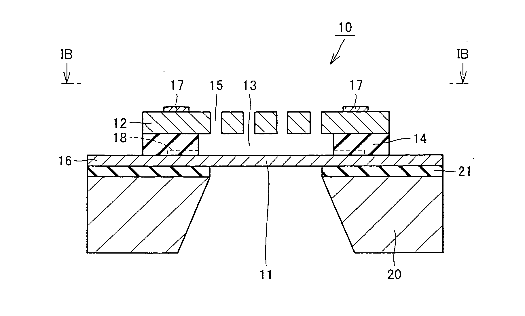
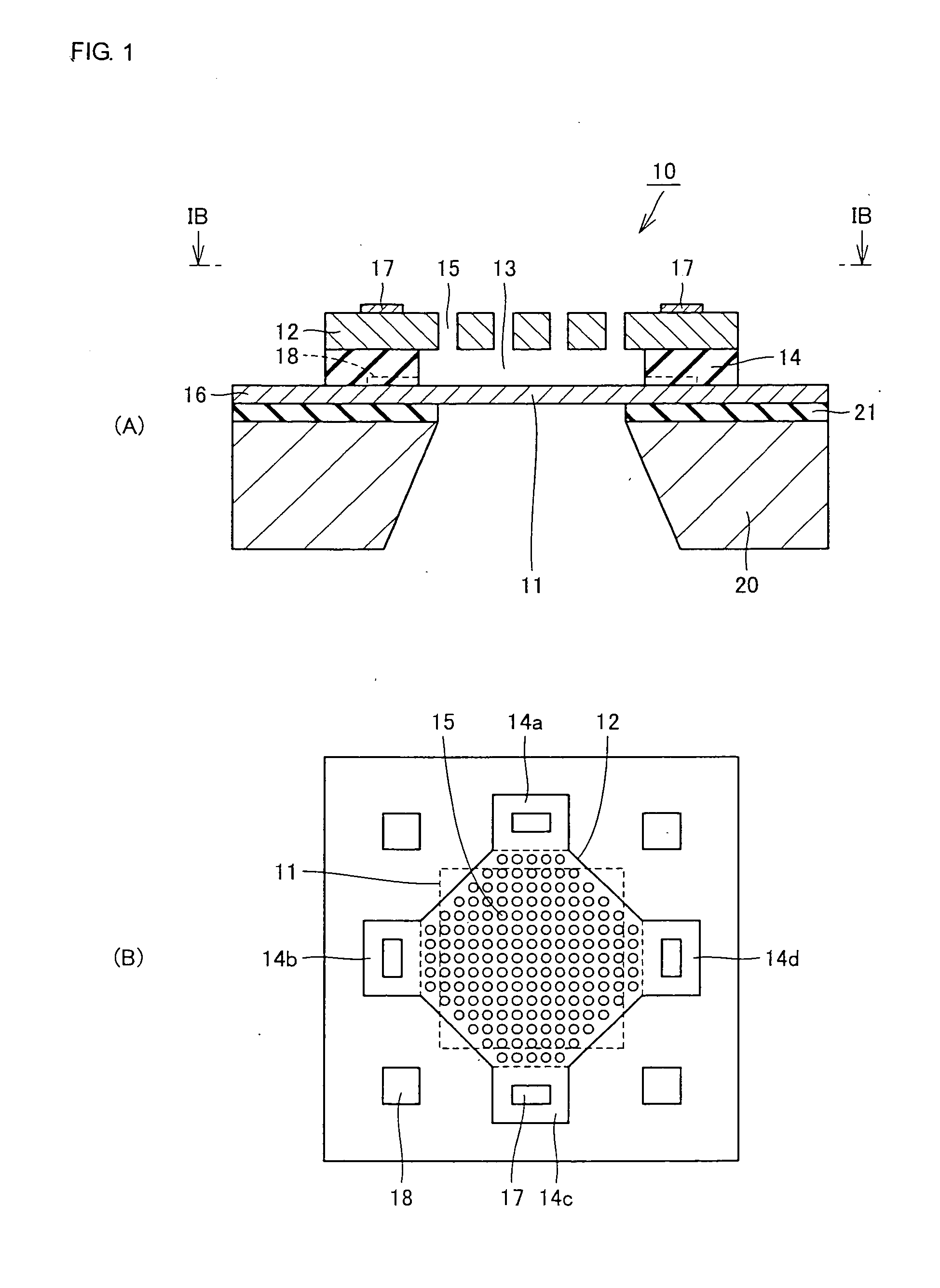
[0019] Hereinafter, embodiments of the present invention will be described with reference to the accompanying drawings. FIG. 1 (A) and FIG. 1 (B) are diagrams to show structure of a microphone which is one example of the capacity detection type sensor element according to one embodiment of the present invention, and FIG. 1 (A) is a cross sectional view and FIG. 1 (B) is a plan view of a section shown by a line IB-IB in FIG. 1(A).

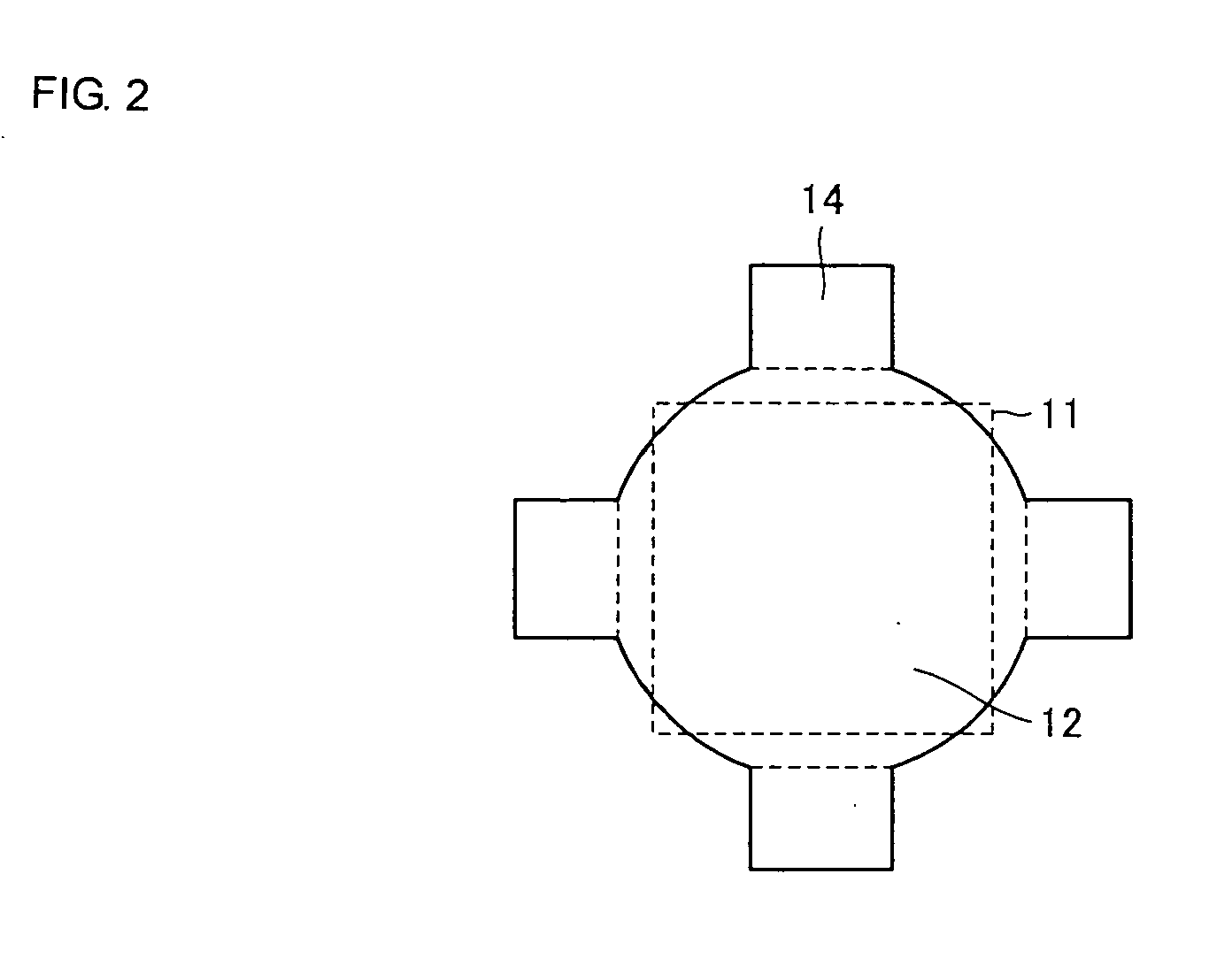
[0020] At first, referring to FIG. 1 (A), the microphone 10 includes a substrate 20, an oxide film 21 which is formed on the substrate 20, a vibrating plate 11 (containing an extended portion 16 extending outwardly from the vibrating plate) which is formed on the oxide film 21, a fixing portion 14 which is provided on the vibrating plate 11 and formed of insulating material and a back electrode 12 which is provided on the fixing portion 14. By the fixing portion 14, a space 13 is formed between the vibrating plate 11 and the back electrode 12. A plurality o...


PUM

PropertyMeasurementUnit
diametersaaaaaaaaaa
diametersaaaaaaaaaa
diameteraaaaaaaaaa

Abstract

A capacity detection type sensor element includes a rectangular vibrating plate, a flat back electrode which are provided opposedly with each other, and fixing portions which are provided adjoining to the vibrating plate, and has a predetermined length A of edge at a side adjoining to the vibrating plate. The back electrode is held by the fixing portions in a state that space is provided between the back electrode and the vibrating plate. Outer edges of the back electrode which are not held by the adjoining fixing portions, are straight lines and the straight lines define an octagonal shape as a whole.

Description

TECHNICAL FIELD [0001] The present invention relates to a capacity detection type sensor element, and more particularly, to a capacity detection type sensor element which is capable of reducing influence of film stress caused by a film which constitutes back electrode of the sensor. BACKGROUND ART [0002] As one example of a capacity detection type sensor element in the prior art technology, a pressure sensor is disclosed in Japanese Unexamined Patent Publication 2002-027595. [0003]FIG. 5 are a plan view (A) and a sectional view (B) of the conventional capacity detection type sensor element which is disclosed in the Patent Publication 2002-027595. [0004] Referring to FIG. 5, the capacity detection type sensor element in the prior art technology comprises a substrate 120, a vibrating plate 111 which is provided in the central part of the substrate 120 and having a small thickness, a back plate (hereinafter also referred to as a back electrode) 112 which is provided to be opposed to th...

Claims


Application Information

Patent Timeline
Patent Type & Authority Applications(United States)
IPC IPC(8): G01L9/12G01L9/00H04R19/00H04R19/04
CPCH04R19/04H04R19/005G01L9/12
Inventor KAGAWA, KENICHIYAKABE, MASAMISAEKI, SHINICHIOHTSUJI, TAKAHISA
Owner TOKYO ELECTRON LTD
Why Eureka
Try Eureka