Bicycle control device

a control device and bicycle technology, applied in the direction of steering devices, cycle equipment, optical signals, etc., can solve the problems of user operable control units, easy removable electrical units, and electric shift control devices of these patents

Active Publication Date: 2007-08-23
SHIMANO INC
View PDF16 Cites 34 Cited by
  • Summary
  • Abstract
  • Description
  • Claims
  • Application Information

AI Technical Summary

Benefits of technology

[0007] One object of the present invention is to provide a bicycle control device that has an electrical uni

Problems solved by technology

However, the electrical shift control devices of these patents do not include an easily

Method used


Image

  • Bicycle control device
  • Bicycle control device
  • Bicycle control device

Examples


Embodiment Construction

[0030] Selected embodiments of the present invention will now be explained with reference to the drawings. It will be apparent to those skilled in the art from this disclosure that the following descriptions of the embodiments of the present invention are provided for illustration only and not for the purpose of limiting the invention as defined by the appended claims and their equivalents.

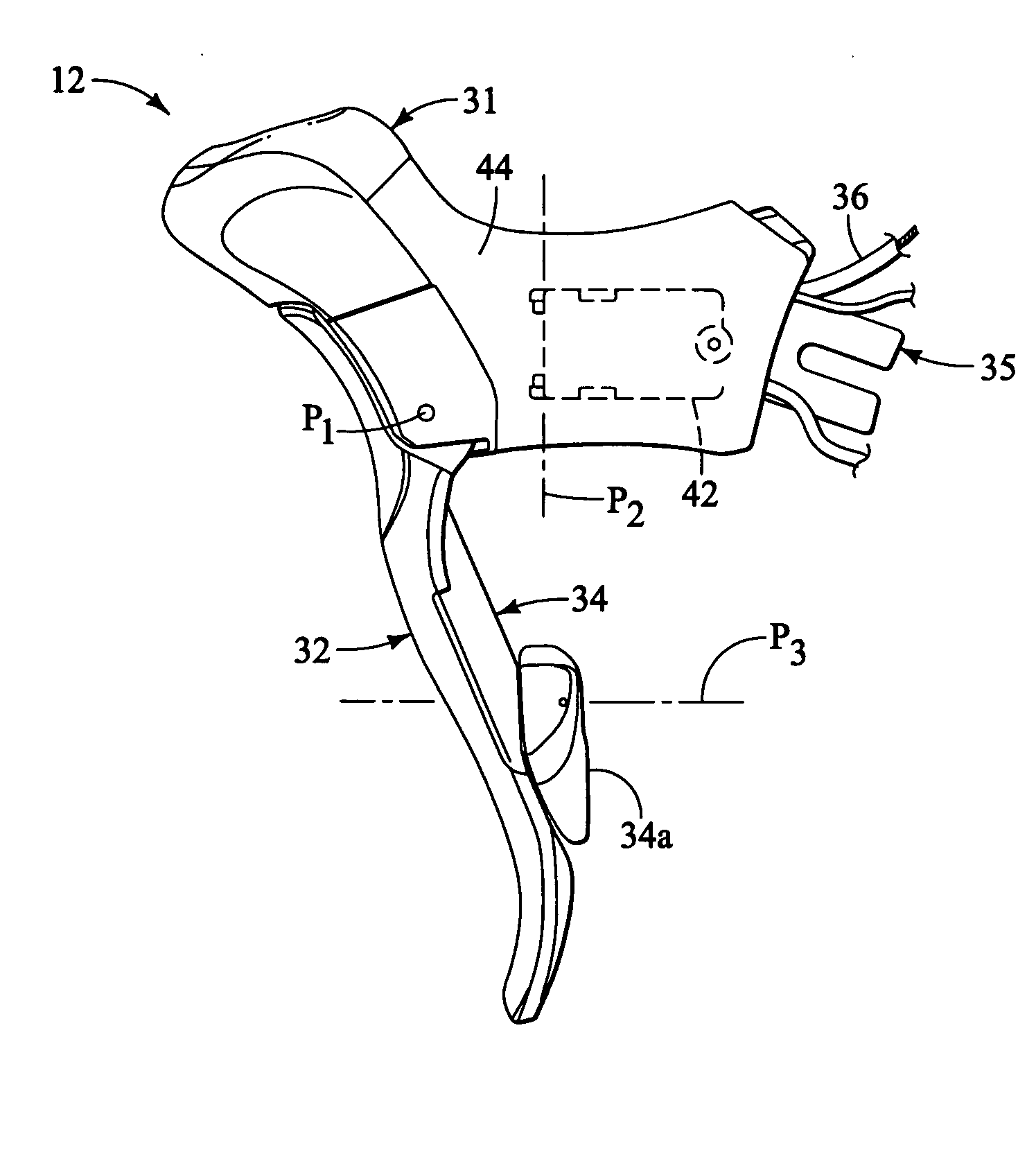
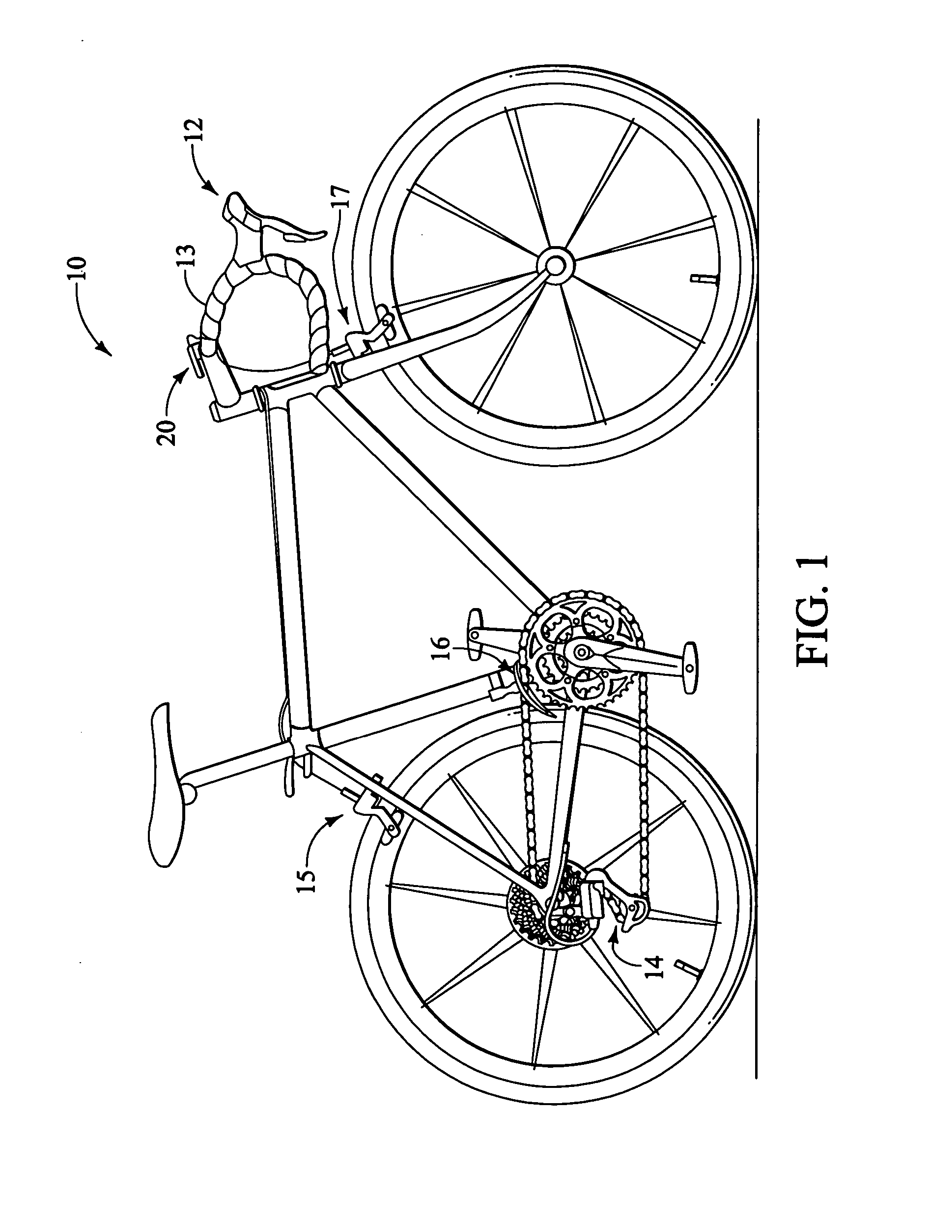
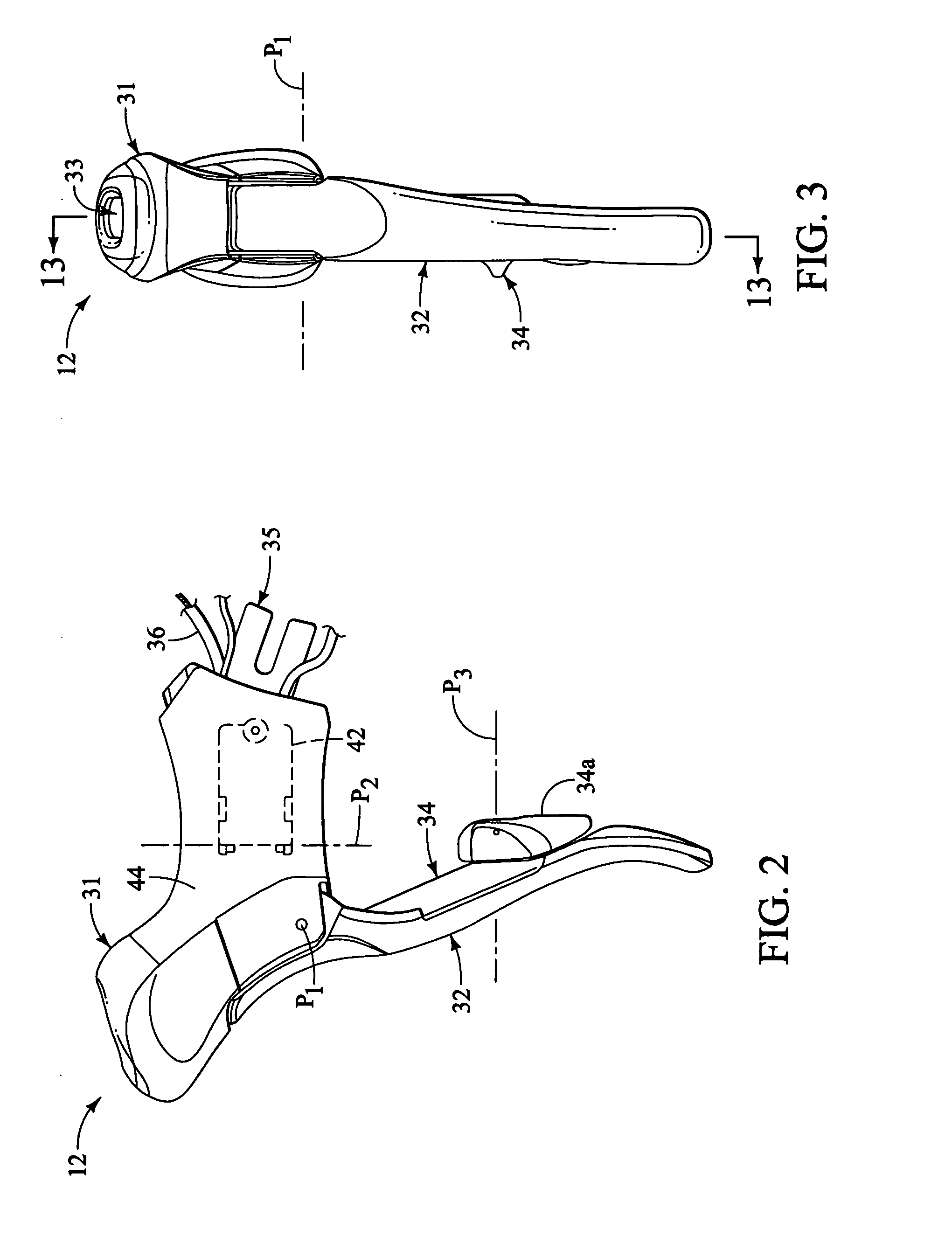
[0031] Referring initially to FIG. 1, a bicycle 10 is illustrated with a pair of control devices 12 (only one shown in FIG. 1) mounted in a bicycle handlebar 13 in accordance with one embodiment of the present invention. One of the control devices 12 is operatively coupled to a rear electronic derailleur 14 and a rear braking device 15, while the control device 12 is operatively coupled to a front electronic derailleur 16 via and a front braking device 17. The right and left hand side control devices 12 are essentially identical in construction and operation, except that they are mirror images. T...


PUM


Abstract

A bicycle control device is provided with a lever bracket and an electrical unit. The lever bracket is movably supporting the control lever. The electrical unit is coupled to the lever bracket. The lever bracket includes a bracket body and a bracket lid. The bracket body has a rearwardly located bicycle mounting portion, a control lever mounting portion and a forwardly located unit mounting portion containing the electrical unit. The bracket lid is releasably coupled to a forwardly face of the unit mounting portion of the bracket body to at least partially enclose the electrical unit in the unit mounting portion of the bracket body.

Description

BACKGROUND OF THE INVENTION [0001] 1. Field of the Invention [0002] This invention generally relates to control devices for bicycles. More specifically, the present invention relates to control devices for bicycles that include a display unit with a display screen being visible in normal use. [0003] 2. Background Information [0004] Bicycling is becoming an increasingly more popular form of recreation as well as a means of transportation. Moreover, bicycling has become a very popular competitive sport for both amateurs and professionals. Whether the bicycle is used for recreation, transportation or competition, the bicycle industry is constantly improving the various components of the bicycle, especially the bicycle control devices for shifting and braking. [0005] In the past, bicycle shifters were mechanically operated devices that were sometimes located near the brake levers of the bicycle. Thus, an operating force was typically applied by one of the rider's fingers to operate a sh...

Claims


Application Information

Patent Timeline
IPC IPC(8): F16C1/12B62J11/19B62J99/00
CPCB62K23/06B62M25/04Y10T74/2042Y10T74/20438Y10T74/20822B62M25/08
Inventor FUJII, KAZUHIRO
Owner SHIMANO INC
Why Eureka
Try Eureka