Valve deactivation device

a deactivation device and valve technology, applied in the direction of valve arrangements, machines/engines, output power, etc., can solve the problems of inability to provide the needed structure, deactivation devices are expensive to produce and assemble, and cannot meet the needs of the user, so as to avoid objectionable noisy operation, increase the hertzian contact stress, and ensure the effect of smooth operation

Inactive Publication Date: 2007-08-23
GENTEK TECH MARKETING
View PDF12 Cites 26 Cited by
  • Summary
  • Abstract
  • Description
  • Claims
  • Application Information

AI Technical Summary

Benefits of technology

[0009] According to the invention, it is necessary that a close control of the lateral clearance between the rocker arm sections and mechanical lash within the valve deactivating device be maintained. The control and mating of the lateral clearance between the rocker arm sections is a prerequisite to ensure adequate engagement of the locking pin within the two rocker arm sections in order to provide adequate locking mechanism durability and overall rocker arm assembly mechanical stiffness.
[0011] The control of mechanical lash, the clearance between the lock pin in one section and that of the surface receiving the lock pin in the other section of the rocker arm, is a pre-requisite to providing smooth functioning avoiding objectionable noisy operation and preventing excessive wear. Referring to the prior art cam mechanism disclosed in the above referenced UK Patent Application GB 2,333,322A, a stop is provided on one of the valve actuator and cam follower sections of the rocker arm to define a limit position in which the locking pins align with their mating bores. However, this reference provides no disclosure of any means to limit the mechanical lash or clearance between the locking pins of either cam follower section and of their mating surfaces in the valve actuator section. This clearance can be and often is found to prove considerable and thus excessive due to manufacturing variation of the rocker arm sections, especially with respect to the location of the locking pin bores, piston bores, rocker shaft bores, and the diameter of the locking pins. In addition, because the cam mechanism described in UK Patent Application GB 2,333,322A comprises two separate locking pins, if the mechanical lash at each locking pin is not identical, only one locking pin will engage the mating surface of the locking mechanism with the result that only one of the two locking pins transfers the entire load from the cam follower section to the valve actuator section. This increases the Hertzian contact stress at the locking pin mating surfaces, substantially decreasing the load carrying capacity and durability of the rocker arm assembly.

Problems solved by technology

Many prior art valve deactivation devices undesirably include numerous components that make the devices costly to produce and assemble.
Still other prior art devices operate by decoupling components of rocker arms that may not necessarily realign properly in order to recouple and reactivate the rocker arm.
Other valve deactivation devices, because of their configuration, are not capable of providing the needed structure to provide suitable tolerances in mating of parts to provide proper function and avoid objectionable noisy operation and unacceptable wear in modern high efficient engines.

Method used


Image

  • Valve deactivation device
  • Valve deactivation device
  • Valve deactivation device

Examples


Embodiment Construction

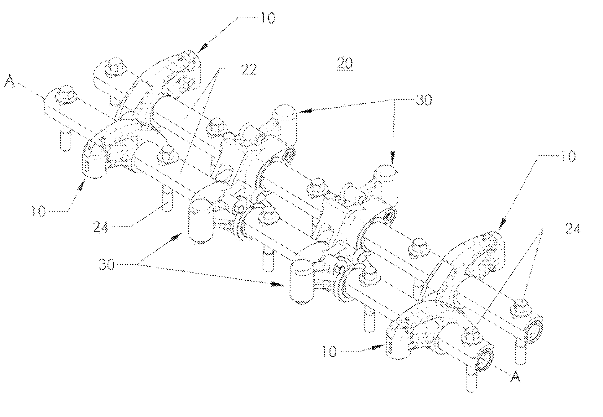
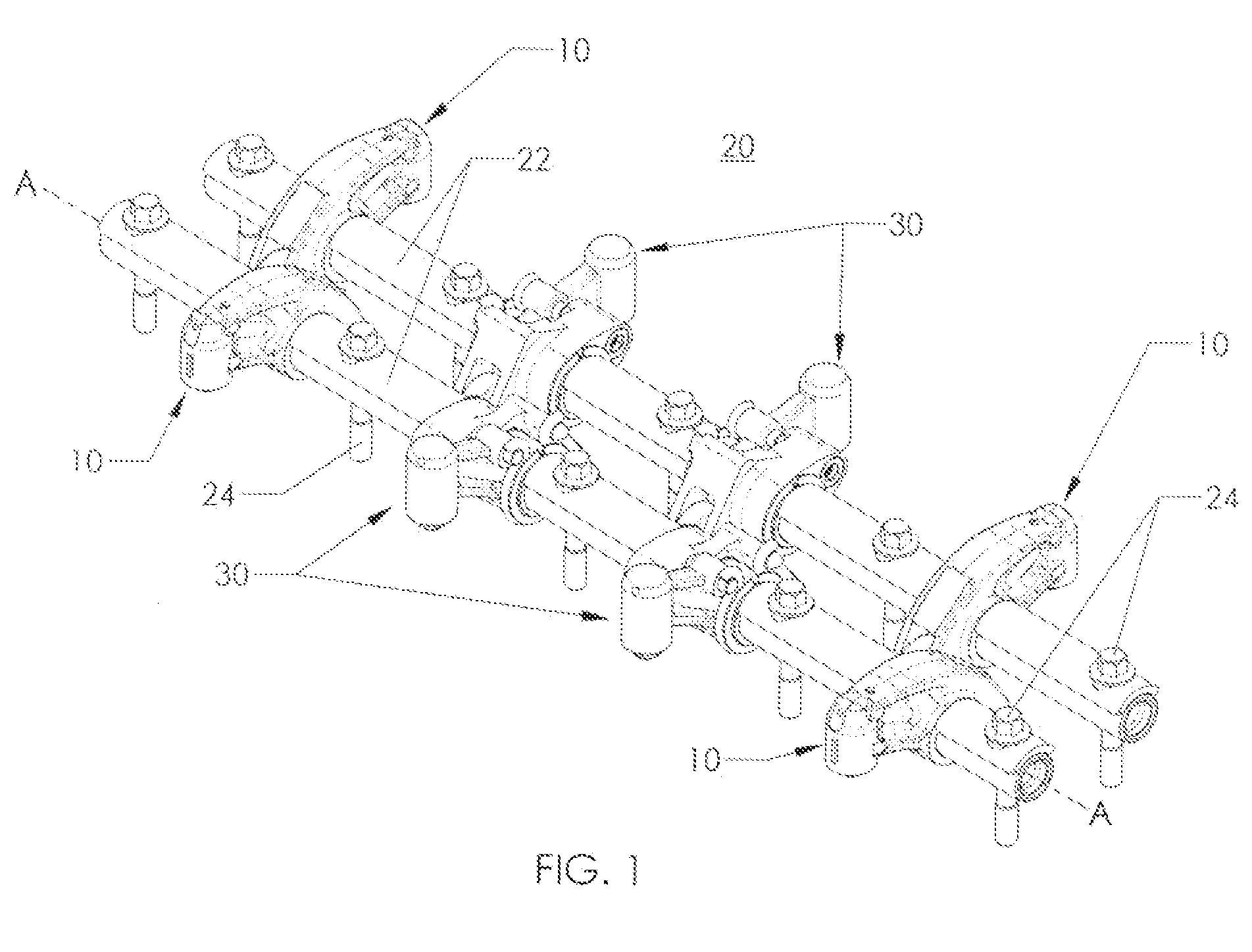
[0020] In the mechanism of the invention, the cam follower and valve actuator sections of the rocker arm are not independent of the rocker shaft and as noted above comprise three forms, each creating a rocker arm assembly which is in turn mounted on the rocker shaft for free rotation about it.

[0021] In the first form, the rocker arm assembly comprises the valve actuator section and cam follower section are mounted on and secured to a tube. In the second form, the valve actuator for the rocker arm assembly is created by a tube element onto which the cam follower section is mounted and secured thereon. In the third form, the cam follower section for the rocker arm assembly comprises a tube element onto which the valve actuator section is mounted and secured thereon.

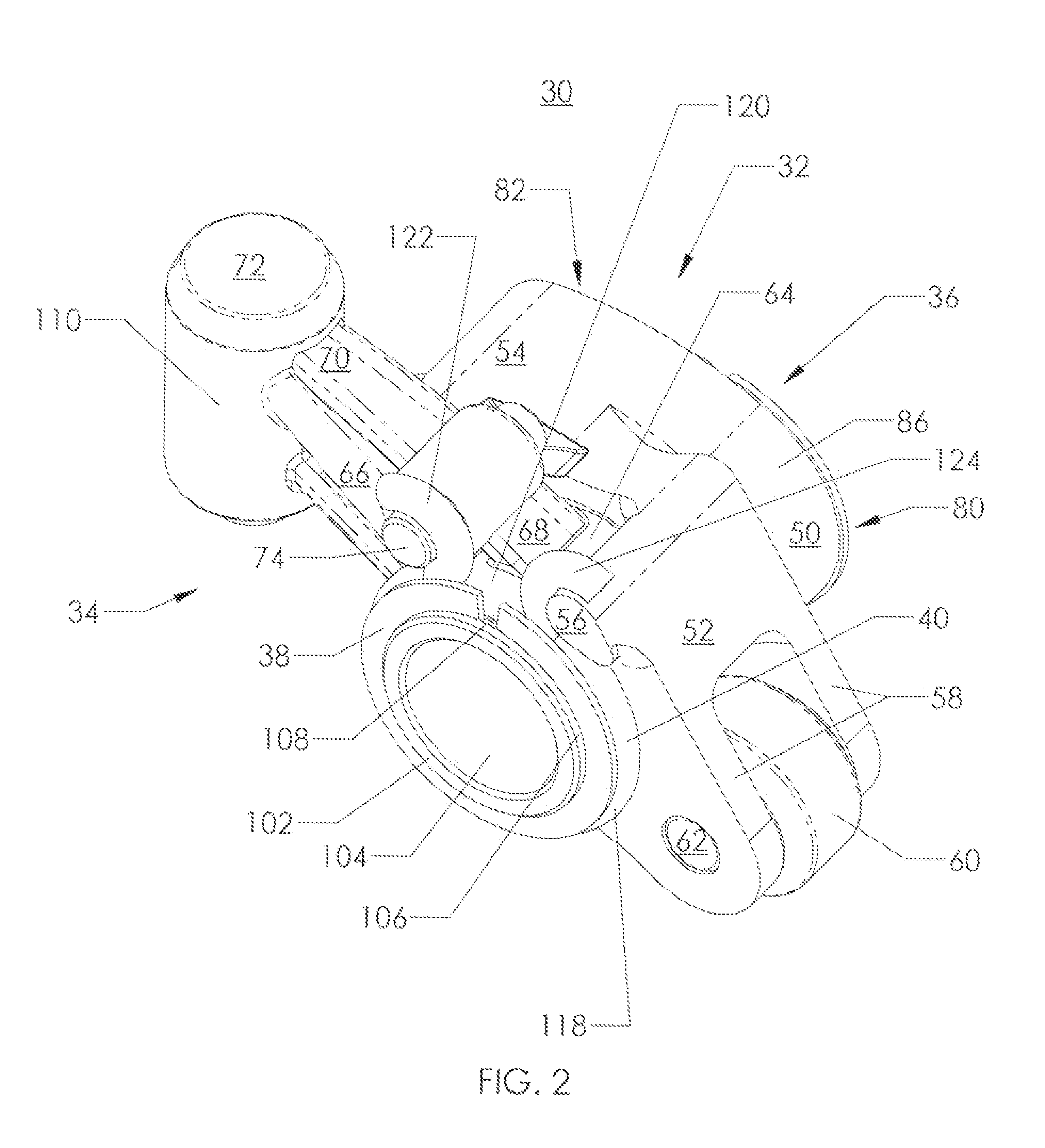
[0022] It is necessary to create a rocker arm providing control of both (a) the lateral clearance between the two rocker arm sections, and (b) the clearance or mechanical lash between the locking pin in one section and th...


PUM


Abstract

A valve deactivation device for a rocker arm assembly having a cam arm and a valve arm is provided. A return spring biases a locking latch pin toward an activated position to allow the cam arm and the valve arm to rotate together. The latch pin can be translated against the biasing force of the return spring to decouple the cam arm and valve arm for relative rotation. The latch pin and the latch pin housing are adjusted so as to limit the clearance between them and mate the latch pin and the latch housing. The cam follower and the actuator section of the rocker arm are mounted on, and are not independent of, the rocker shaft. Clearances between parts are controlled such that their relative rotation is strictly limited in the selective engagement of the latch pin in one section and latch pin receiving hole in the other section.

Description

CROSS REFERENCE TO RELATED APPLICATIONS [0001] This application is a Continuation-in-Part of U.S. application Ser. No. 11 / 060,663 filed on Feb. 17, 2005; which claims the benefit of U.S. Provisional Application Ser. No. 60 / 545,739, filed on Feb. 18, 2004, and U.S. Provisional Application Ser. No. 60 / 546,692, filed on Feb. 20, 2004, the contents of which are incorporated in their entireties by reference.FIELD OF THE INVENTION [0002] The present invention relates to valve trains for internal combustion engines. More particularly, the present invention relates to an improved valve deactivation device for use in a valve train for internal combustion engines. BACKGROUND OF THE INVENTION [0003] Modern multi-cylinder internal combustion engines include a valve train having intake and exhaust valves disposed in the cylinder head above each combustion cylinder. The intake and exhaust valves connect intake and exhaust ports with each combustion cylinder. The intake and exhaust valves are gene...

Claims


Application Information

Patent Timeline
Patent Type & Authority Applications(United States)
IPC IPC(8): F01L1/34F01L1/18F02D17/02F01L13/00
CPCF01L1/181F01L13/0005F01L2820/033F01L2105/00F01L2001/186F01L2305/00
Inventor BEST, RICHARD R.
Owner GENTEK TECH MARKETING
Why Eureka
Try Eureka