
Engine air intake arrangement for a vehicle

a technology for engine air intake and vehicle, which is applied in the field of vehicle, can solve the problems of inhibiting a decrease in intake efficiency, and achieve the effects of preventing air infiltration, facilitating the installation of stationary funnels to the engine, and ensuring stiffness

Active Publication Date: 2007-08-23
YAMAHA MOTOR CO LTD
View PDF4 Cites 11 Cited by
  • Summary
  • Abstract
  • Description
  • Claims
  • Application Information

AI Technical Summary

Benefits of technology

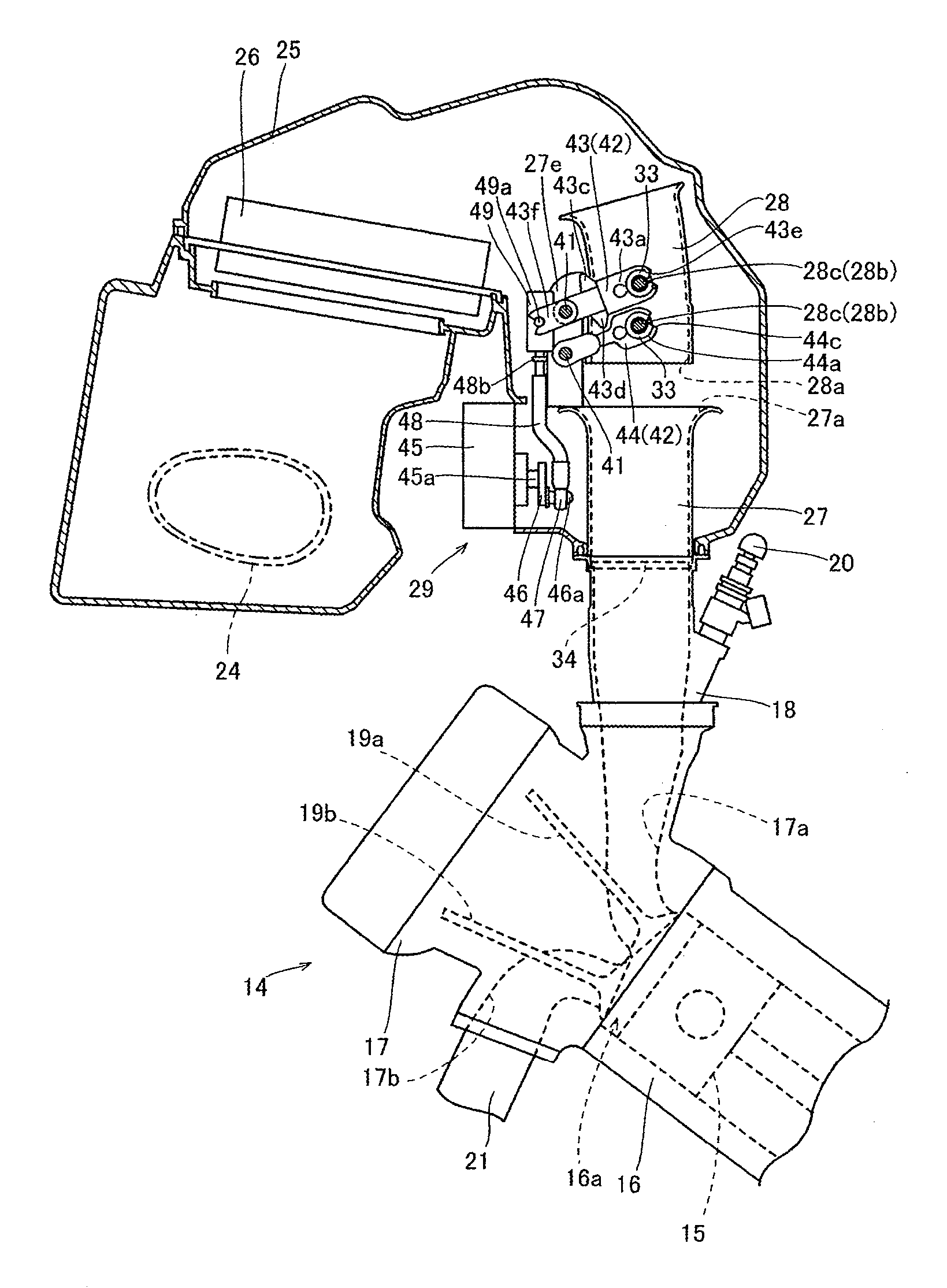
[0010] One aspect of the present invention involves the realization by the present inventors that with constructions substantially similar to that disclosed in Japanese Patent Publication No. 09-100720 and FIGS. 36 and 37, the flow resistance of the air is increased when the movable funnel 102 is separated from the stationary funnel 101 (that is, when the engine 100 rotates at high speeds). Specifically, with such constructions, the single turning lever 105 rotates the movable funnel 102 such that outlet 102a end portion of the movable funnel 102 is inclined with respect to the inlet 101a end portion of the stationary funnel 101 when the movable funnel 102 is separated from the stationary funnel 101. Therefore, the air passing through the movable funnel 102 and passing into the stationary funnel 101 is bent in a flow direction, and the flow resistance of the air is increased. Consequently, when the movable funnel 102 is separated from the stationary funnel 101, there exists a decrease in intake efficiency.

Problems solved by technology

Consequently, when the movable funnel is separated from the stationary funnel, it is possible to inhibit a decrease in intake efficiency.
Consequently, in the case where the engine rotates at high speed, it is possible to inhibit a decrease in intake efficiency.

Method used


Image

  • Engine air intake arrangement for a vehicle
  • Engine air intake arrangement for a vehicle
  • Engine air intake arrangement for a vehicle

Examples


first embodiment

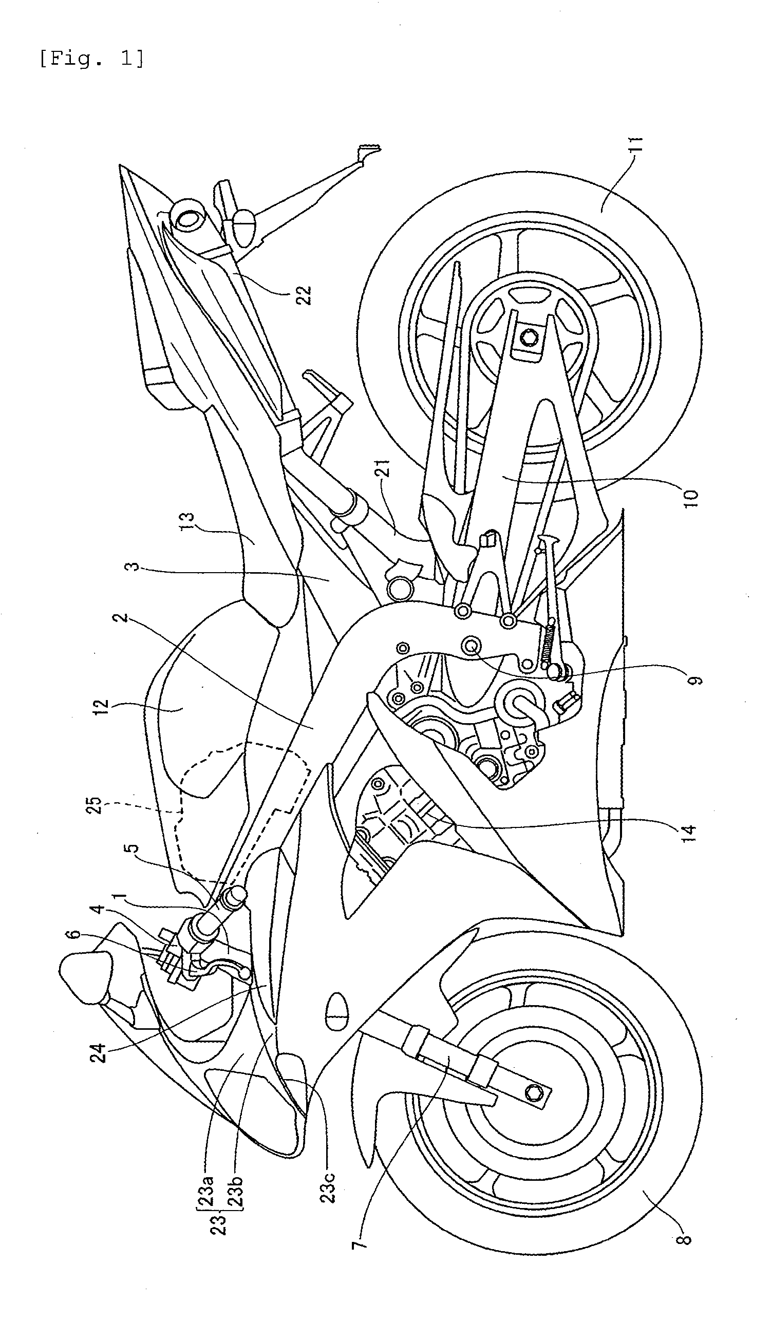
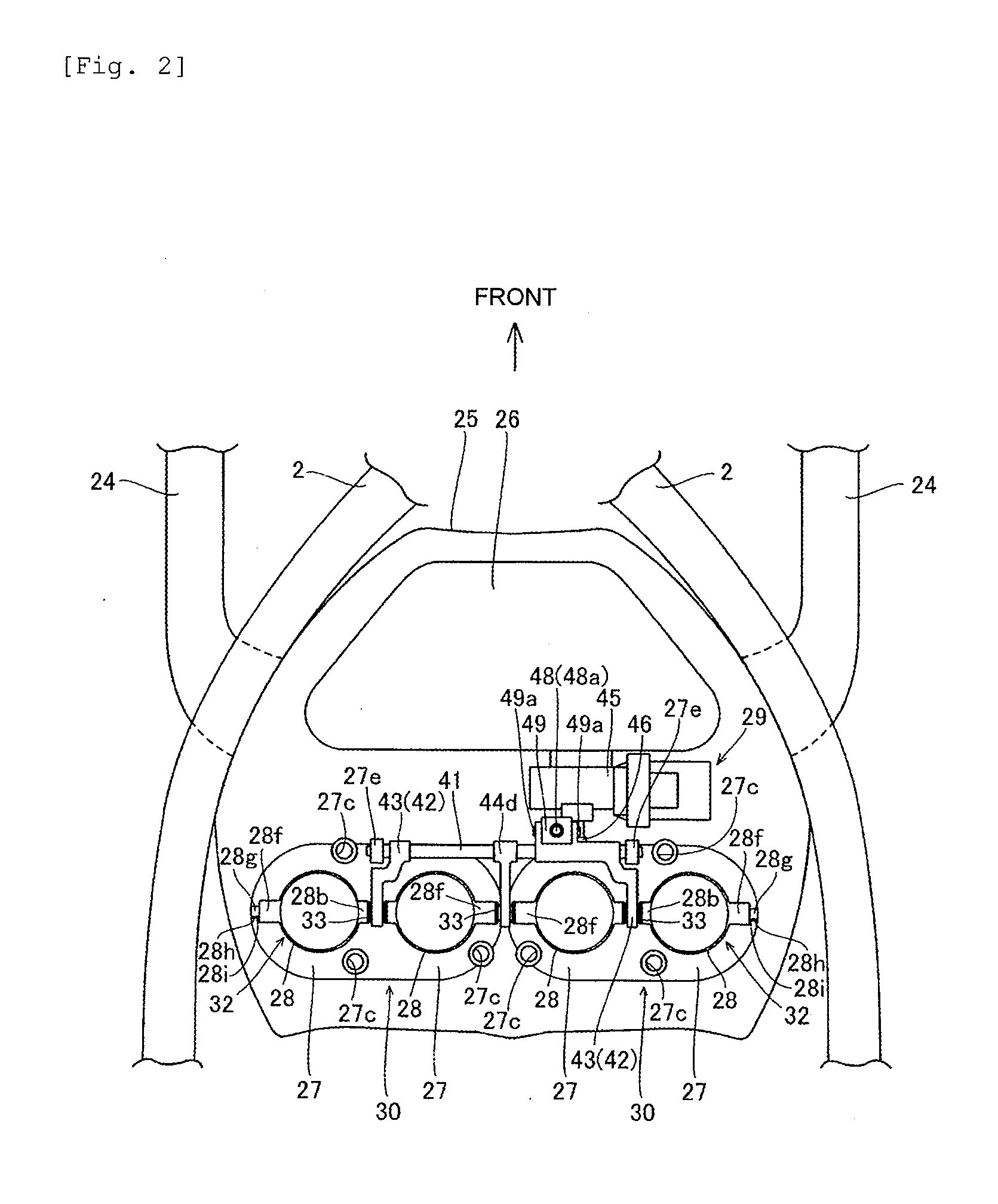
[0072] In the construction of the motorcycle according to the invention, a front end of a main frame 2 is connected to a head pipe 1 as shown in FIG. 1. The main frame 2 is arranged so as to branch and extend left and right toward the front of a vehicle as shown in FIG. 2. The main frame 2 is formed so as to extend rearwardly and downward as shown in FIG. 1. Also, a seat rail 3 is connected to the main frame 2 to extend rearwardly and upward. A steering mechanism portion 4 is mounted to the head pipe 1 to be rotatable. A handle 5 is mounted to an upper side of the steering mechanism portion 4. A clutch lever 6 is mounted to the handle 5. Also, a front fork 7 is mounted to a lower side of the steering mechanism portion 4. A front wheel 8 is mounted rotatably to a lower end of the front fork 7.

[0073] A front end of a swing arm 10 is mounted to a rear end of the main frame 2 through a pivot shaft 9. A rear wheel 11 is mounted rotatably to a rear end of the swing arm 10. A fuel tank 12 ...

second embodiment

[0133] Also, while the second embodiment illustrates an example in which a single flat surface portion is provided on the rotating shaft, the invention is not limited thereto but a plurality of flat surface portions may be provided on the rotating shaft.

[0134] Also, while according to the second embodiment the respective joints 61b of the upper and lower rotating shafts 61, to which the rotating shaft insertion holes 63b of the upper linkage members 63 and the rotating shaft insertion holes 64b of the lower linkage members 64 are mounted, are structured to include the flat surface portions 61c, the invention is not limited thereto but a plurality of irregular portions 71c provided in an outer circumferential direction of a rotating shaft 71 by means of knurling may be included in joint portions 71b like the rotating shaft 71 according to a modification of the second embodiment. The plurality of irregular portions 71c enable readily inhibiting an upper linkage member 73 and a lower l...


PUM


Abstract

A vehicle, such as a motorcycle, includes one or more stationary funnels through which air is delivered to an intake port of an engine. One or more movable funnels are arranged on an inlet side of the one or more stationary funnels and cooperating with the stationary funnels to deliver air to the intake port of the engine. A parallel linkage rotatably supports the stationary funnels and includes an upper linkage member and a lower linkage member.

Description

RELATED APPLICATIONS [0001] This application claims priority from Japanese Patent Application Nos. 2006-253638, filed Sep. 20, 2006, and 2006-009139, filed Jan. 17, 2006, the entireties of which are incorporated by reference herein. This application is also related to U.S. application Ser. Nos. FY.52939US2A and FY.52939US3A, filed on even date herewith, and entitled ENGINE AIR INTAKE ARRANGEMENT FOR A VEHICLE, the entireties of which are incorporated by reference herein.BACKGROUND OF THE INVENTION [0002] 1. Field of the Invention [0003] The present invention relates to a vehicle, and more particular, to a vehicle provided with a funnel through which the air is delivered to an intake port of an engine. [0004] 2. Description of the Related Art [0005] It is conventional for vehicles, such as motorcycles, for example, to be provided with a funnel through which the air is delivered to an intake port of an engine. For example, Japanese Patent Publication No. 09-100720 discloses a motorcyc...

Claims


Application Information

Patent Timeline
Patent Type & Authority Applications(United States)
IPC IPC(8): B62K11/00
CPCF02B27/0231F02B27/0294F02D9/12F02M35/02491F02M35/10039F02M35/10052F02B27/0215F02M35/10104F02M35/10216F02M35/10301F02M35/162Y02T10/146F02M35/10065Y02T10/12
Inventor YOKOI, MASATO
Owner YAMAHA MOTOR CO LTD
Learn More