Three-axis antenna, antenna unit, and receiving device

a three-axis antenna and antenna unit technology, applied in the direction of antennas, antenna details, antenna adaptation in movable bodies, etc., can solve the problems of increased thickness in the above-mentioned structure, unsuitable for miniaturization in terms of height, etc., to achieve easy orientation, enhance antenna sensitivity, avoid coupling of each arm

Active Publication Date: 2007-08-23
SUMIDA CORP
View PDF2 Cites 25 Cited by
  • Summary
  • Abstract
  • Description
  • Claims
  • Application Information

AI Technical Summary

Benefits of technology

[0019] Miniaturization in terms of height can be attained since the windings do not overlap in the antenna coil unit and the receiving device pursuant to the present invention. The head section of the X-axis arm and the head section of the Y-axis arm are retained when the cross-shaped core is set in a case with a bottom, and a retaining tab that determines the position in the Z-axis direction of the X-axis arm and the Y-axis arm is provided. Consequently, the cross-shaped core, X-axis arm and Y-axis arm can be easily oriented in the vertical direction, and coupling of each arm can be avoided, thereby attaining sensitivity without deviation concerning any of the XYZ axis winding wires.
[0018] The three-axis coil, antenna coil unit and receiving device pursuant to the present invention are provided with a Z-axis winding wire provided in a condition so as to cover the entire head surfaces of the X-axis arms and head surfaces of the Y-axis arms in the cross-shaped core, the X-axis winding wire and Y-axis winding wire each begin from the root section of an arm and extend toward the head section of the arm without encircling said head section. Each winding then spans to the head section of the other arm from which point it continues toward aforementioned root section. Thus, the potential becomes equal at the head section of a pair of X-axis arms and at the head section of a pair of Y-axis arm and the effects of the electric field due to the head section of aforementioned X-axis arm and to the head section of aforementioned Y-axis arm on the Z-axis winding wire provided in a condition enclosing aforementioned cross-shaped core outside the head sections of the X-axis arms and the head sections of the Y-axis arms are equal, thereby attaining sensitivity without deviation concerning the Z axis winding wire.
[0019] Miniaturization in terms of height can be attained since the windings do not overlap in the antenna coil unit and the receiving device pursuant to the present invention. The head section of the X-axis arm and the head section of the Y-axis arm are retained when the cross-shaped core is set in a case with a bottom, and a retaining tab that determines the position in the Z-axis direction of the X-axis arm and the Y-axis arm is provided. Consequently, the cross-shaped core, X-axis arm and Y-axis arm can be easily oriented in the vertical direction, and coupling of each arm can be avoided, thereby attaining sensitivity without deviation concerning any of the XYZ axis winding wires.

Problems solved by technology

However, the thickness is increased in aforementioned structure because the winding in one axis overlaps the winding in the other axis in a two-axis antenna, which makes it unsuited for miniaturization in terms of height.

Method used


Image

  • Three-axis antenna, antenna unit, and receiving device
  • Three-axis antenna, antenna unit, and receiving device
  • Three-axis antenna, antenna unit, and receiving device

Examples


embodiment 1

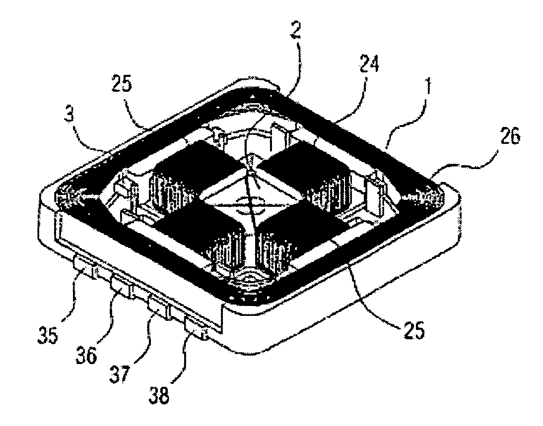
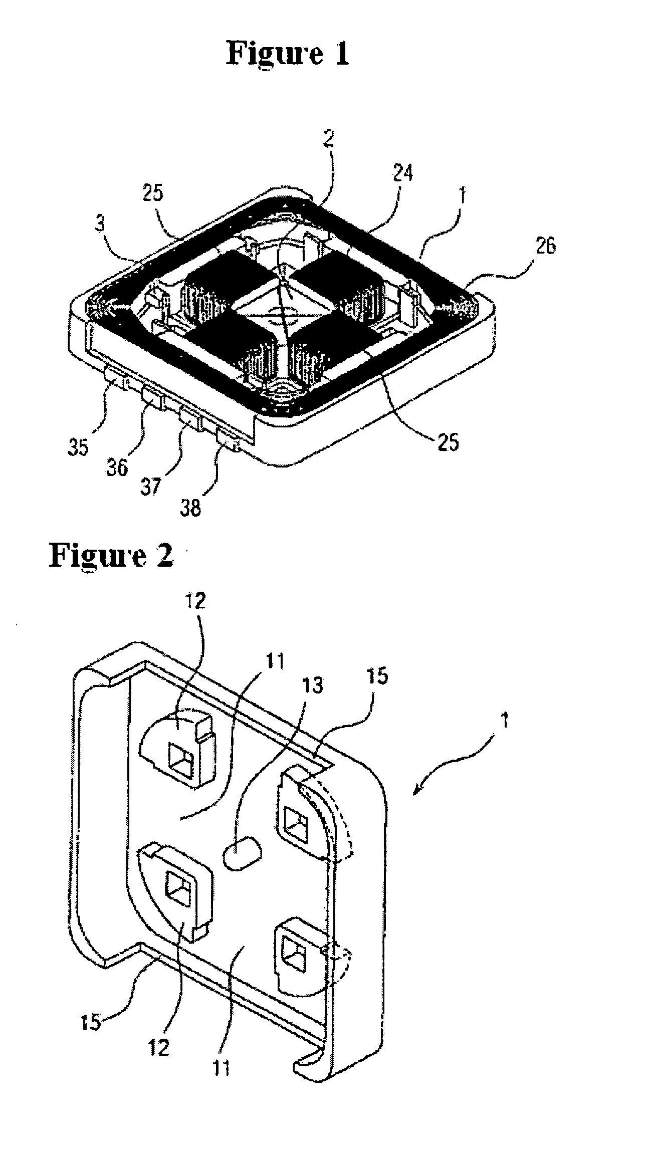
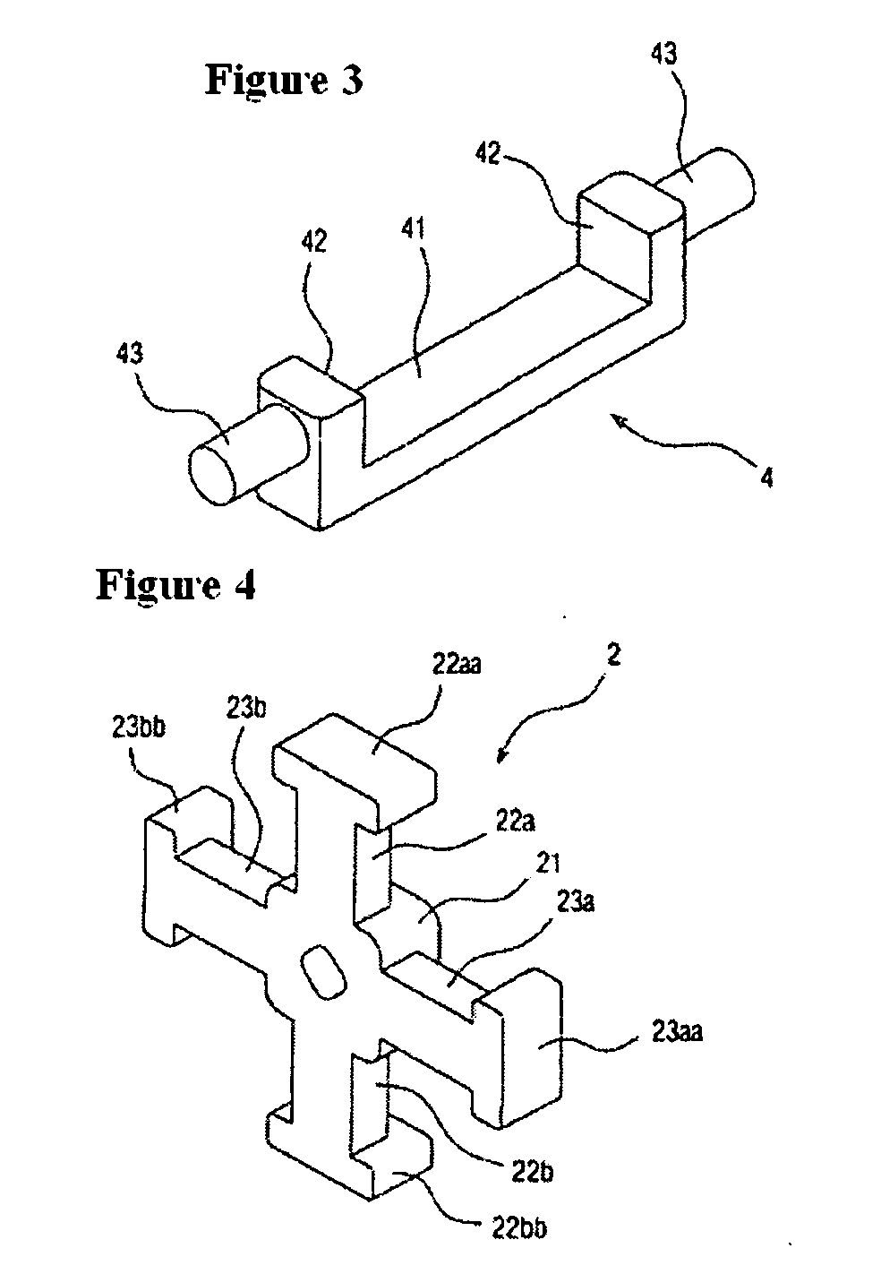
[0021]FIG. 1 presents the antenna coil unit pursuant to Embodiment 1 of the present invention. Case 1, as shown in FIG. 2, a perspective diagram, is a roughly square case with a bottom having a pair of notches cut in the side walls. It may be constructed of resin, for example. Convex members 12 with a one-quarter fan shape are formed in the bottom of case 1 at the four corners to divide the bottom into roughly nine equal portions. Grooves 11 are formed among these convex members 12 so as to match the cross shape of cross-shaped core 2 in order to house aforementioned cross-shaped core 2 shown in FIG. 5 with the completed winding. Cross-shaped core 2 has a prismatic-shaped base section 21 in the center, as shown in FIG. 4. X-axis arms 22a, 22b and Y-axis arms 23a, 23b extend outward in four directions at 90-degree angles from base section 21. In addition, projection 13 that is formed in the center of the bottom of case 1, as shown in FIG. 2, is inserted into a hole formed in base sec...


PUM

PropertyMeasurementUnit
thicknessaaaaaaaaaa
heightaaaaaaaaaa
magnetic fluxaaaaaaaaaa

Abstract

To achieve sensitivity not deviating in any of XYZ directions. A three-axis antenna with a cross-shaped core (2) having a pair of X-axis arms (22a, 22b) projecting in the X-axis direction in an orthogonal coordinate system and a pair of Y-axis arms (23a, 23b) projecting in the Y-axis direction orthogonal to the X-axis direction, and having Z-axis winding wire (26) provided in a substantially rectangular frame shape, outside the head sections of the X-axis arms (22a, 22b) and the head sections of the Y-axis arms (23a, 23b). The Z-axis winding wire is housed in a case having the bottom so as to cover the entire parts of head surfaces of the X-axis arms (22a, 22b) and of head surfaces of the Y-axis arms (23a, 23b).

Description

TECHNICAL FIELD OF INVENTION [0001] The present invention concerns a three-axis antenna, antenna unit and receiving device used in keyless entry systems for wireless operation of locking and unlocking automobile doors, for example. BACKGROUND TECHNOLOGY [0002] Three axial windings are completed about one core in conventional three-axis antennas. A three-axis antenna that combines a two-axis antenna with a one-axis antenna is disclosed in the gazette of Japanese Kokai Publication 2003-92509. However, the thickness is increased in aforementioned structure because the winding in one axis overlaps the winding in the other axis in a two-axis antenna, which makes it unsuited for miniaturization in terms of height. [0003] In contrast, aforementioned literature presents winding about a cross-shaped core as a two-axis antenna. The need for miniaturization in terms of height is addressed by providing an appropriate three-axis antenna using this. Patent literature 1: Gazette of Japanese Kokai...

Claims


Application Information

Patent Timeline
Patent Type & Authority Applications(United States)
IPC IPC(8): H01Q7/08H01F3/00H01Q1/32H01Q21/24
CPCH01F3/00H01F2003/005H01Q21/24H01Q7/08H01Q1/3233H01Q7/06
Inventor UEDA, HOZUMI
Owner SUMIDA CORP
Why Eureka
Try Eureka